How to control LP and HP control valves in Woodward governor
Steam Turbine Control Valve, Governing and Lube Oil System
General industrial steam turbine prefers a steam source of 42 Kg/Cm2 (600 PSI) at 482 OC (900 o F).
Steam turbines for industrial applications are often classified in two (2) categories, according to the basic design-
1) Condensing turbine where the steam exhausts into a condenser. A vacuum in the condenser provides the optimum pressure drop from turbine inlet to turbine exhaust. The steam condenses to water and a pump returns this water to the boiler.
2) Back pressure turbine is the turbine where the exhaust of the turbine is above atmosphere. The low pressure exhaust stream is utilized to some other section of the plant. Typical pressure is 2 to 4 kg/cm2 for heating a process or heating a building.
This article covers Controls for Turbine for a variety of functions and therefore it would be natural to classify the turbines according to the control parameters.
Classification according to Control Function:
-
Condensing turbine, the most common application for driving generator and for mechanical drive (compressor) if no other turbine parameter needs to be controlled.
-
Inlet Pressure control where the turbine has the basic task to maintain a constant pressure in its inlet header.
-
Back Pressure turbine where the turbine has a task to provide a low pressure steam by expanding steam from the high pressure source.
-
Extracting Turbine for applications requiring an intermediate source of steam pressure at a controlled flow.
-
Induction Turbine, also called Admission Turbine where an intermediate source of pressure is available to drive the turbine , in addition to high pressure source.
All these basic types are used in many variations, including extraction turbines with two or more extraction ports or combination of extraction /induction turbines.
Classification according to the number of Valves:
In past during the era of analog controls, the functional classification was natural classification. Actually it was analog controls which was hardware intensive requiring significant design work for a particular application or function. But now all is digital control which is software intensive. This software control eliminated much of this hardware design.
For example, the digital control does not care whether a 4 -20 mA input signal is pressure, power or any other parameter because all the scaling is done in software. Therefore from a control point of view we can simplify the system by classifying the turbine according to the number of control points on the turbine with each control point having one or more control valves.
Each location can have multiple valves, such as a turbine with multiple inlet valves but these valves operate at a single point: the inlet of the turbine. These valves can operate simultaneously or in sequence but in the classification these valves are considered as a single control point. Large, single extraction turbines may have more than one LP valve to handle the steam volume but for this classification all extraction valves at one location are considered as one valve.
1. Single Valve Turbines: Because there is only one controlled (inlet) port, only one parameter can be controlled simultaneously. This single parameter can be speed, inlet pressure, back pressure, or for a compressor drive, that parameter can be a compressor function such as suction pressure or discharge pressure. The control may have additional control functions such as speed and valve opening limiter and the control can switch from one control mode to another which is typical during a start when the control switches from speed control to pressure control. At any given time only one parameter can be in control.
Condensing Turbines: Steam enters the turbine through the inlet valve and exhausts to the condenser. A vacuum pump maintains vacuum of typically 4 inch Hg in the condenser, giving the turbine the pressure drop between inlet and exhaust for optimum efficiency. Cooling water flowing through the condenser converts the exhaust steam to water and a pump returns this water to the boiler. The controlled parameter for the turbine is speed and for Generator drives this is the only parameter. For mechanical drive the controlled parameter shall be also on Compressor, such as compressor suction pressure or compressor discharge pressure.
A single valve condensing type turbine may have an extraction port or even more than one extraction port but this extraction flow is not controlled.
Backpressure Control: Here in this type of turbine, high pressure steam is expanded to low pressure steam. Another technique is to use expansion valves with a pressure regulator but this method is inefficient because it is a waste of heat energy during expansion. The back pressure turbine recovers this energy by driving a useful load.
The steam in the back pressure header is used in a process or for heating purposes, usually at a variable flow demand. There is no instrument available to measure demand but it is known that at constant turbine speed the back pressure would vary with demand. An increase in demand results in an initial decrease in pressure while a decrease in flow demand initially will result in an increase in pressure. Therefore, the control on the backpressure turbine modulates the inlet valve and matches steam flow to steam demand by maintaining constant pressure in the backpressure header.
When the pressure drops, the control will open the inlet valve further until the new flow matches the flow demand and pressure returns to normal. However the increase in steam flow also increases the speed or power output of the turbine.
The main task of the back pressure turbine is to provide low pressure steam. The power available from the expansion of the steam in the turbine is a by-product but for a single valve turbine, as a backpressure turbine this power can not be controlled: the available power depends solely on the demand for extraction steam.
Inlet Pressure Control: The inlet pressure turbine receives its steam from a high pressure header which also provides steam to other users such as other turbines. The flow in the header varies with the demand by these users and rather than varying the flow from the boiler, the inlet pressure turbine takes all these flow. Again, it is not possible to measure flow demand by other users but the inlet pressure turbine matches available flow to flow demand by maintaining constant header pressure. When header pressure drops due to an increase in flow demand, the controller closes the inlet valve. When header pressure increases due to a drop in demand, the controller opens the inlet valve further. Again, the available power is a function of steam flow and can not be controlled in this application.
The back pressure and inlet pressure application work for generators which operate in parallel with a grid and for variable speed mechanical drives. These applications do not work for generators on an isolated system as the control cannot maintain constant speed.
The inlet valve for backpressure turbine opens when the transmitter indicates a drop in pressure. However, the inlet valve of the inlet pressure turbine moves in the opposite direction: it closes when the transmitter on the high pressure header indicates a pressure drop.
Mechanical Hydraulic Governors:
Governor is the basic speed control which receives a pneumatic speed reference signal from a process control. Commonly this is a 3 – 15 PSI signal. This process controller can control any variable such as back pressure, turbine inlet pressure, compressor suction pressure or discharge pressure depending on the operation of the turbine. As the governor is completely mechanical-hydraulic it is intrinsically safe in all hazardous environments. In addition it is completely self-contained as it has an internal oil supply. However, from an operational point this type of governor has some operational limitations as follows.
(1) If the 3- 15 PSI speed reference signal represents compressor operation, the 3 PSI is equivalent to minimum compressor operating speed and 15 PSI represents maximum compressor operating speed.
(2) The dynamics of the governor are determined by mechanical components and the speed range over which the governor will control with acceptable stability is limited.
(3) The governor has an internal oil supply and pump. Therefore, the servo does not have any power output until turbine speed has increased sufficiently to provide adequate oil pressure from the pump.
(4) For stability reasons, there is a time delay between any changes in the speed reference input and the reaction of the internal speed setting mechanism.
(5) Because the 3 PSI signal determines the minimum speed (equivalent to minimum compressor speed) where the governor will control, the start procedure, upto that speed, must be manual through the Trip&Throttle(T&T) valve (installed in steam inlet line). The operator cracks the T&T valve open and the turbine starts rotating. As soon as the oil pump in the governor produces sufficient pressure, the governor senses an underspeed condition and it moves the controlled valve (CV) to maximum. CV is installed in the downstream of TT valve in the steam inlet line. Any ‘Hold’ for warm up and any fast acceleration through a critical must be controlled manually through the T/T valve. This process continues until the turbine reaches a speed corresponding to the 3 PSI reference setting at which point the governor takes control of the turbine through the control valve CV. The Trip & Throttle (T/T) valve can be opened completely and the compressor loading process stars.
In addition any decrease in the turbine speed below the 3 PSI level such as turbine idle or a controlled shutdown must be accomplished manually, again via the T/T valve.
The speed reference input moves a pilot valve (PV) via a bellows. The PV directs oil to the piston on top of the speeder spring (SS) which determines the actual reference setting. A restriction in the flow of oil to this piston creates a time delay. This built-in time delay of 3 – 5 seconds is necessary for system stability but it prevents any fast overriding action via the 3-15 PSI input when a limiter wants to affect the steam valve instantly. A typical example is a steam driven pump which is controlled on flow with an override when suction pressure drops.
Electronic Governors:
This governor was introduced in old days. It is vintage category now. The speed reference for this type of governor was a combination of a remote reference 94 -20 m A) from a process controller and a manual potentiometer, with the later used to control speed below the minimum compressor operating speed corresponding to 4 m A. The electronic governor allowed the operator to control turbine speed through the control valve (CV) over a much wider speed range and also allowed remote control of speed.
Benefit of the electronic speed governor over mechanical hydraulic includes the reaction time and some additional flexibility. The electronic speed control reacts faster than the mechanical – hydraulic equivalent if combined with a fast actuator. It also operates with a wider speed rage.
Digital Controls: Basic control mode-
(1) The normal mode of operation which can be speed, power, pressure, or any other variable as long as it is understood that for a single valve turbine only one parameter can be in control at any given time at any given type although the control must be able to switch from one single control parameter to another.
(2) The control must recognize that there are certain limiting parameters which may have to take over automatically when such a variable reach a set point.
Cascade Control Mode:
Speed is the basic control parameter for both generator and mechanical drive. Any other control parameter such as a process controller acts as a reference input to the speed controller. The output of the process control modulates the reference of the speed control.
Inlet Pressure Control:
Let us consider a turbine connected a constant pressure steam header. When there are other users connected with the steam header, the header pressure drops and the control close the turbine inlet valve which makes more steam available to other users. The main task is to maintain header pressure while the power is a byproduct which depends on the amount of steam through the turbine.
Back Pressure Control:
Back pressure can be controlled as above, except the inversion of the signal must beaded as the turbine control valve moves in the opposite direction: a drop in back pressure indicates an increase in demand which requires the inlet valve to be opened. For the inlet pressure control a drop in pressure requires the valve to move in the close direction.
Minimum Inlet Presser Limiter: In simple speed control of steam turbine, the steam pressure may drop due to a sudden demand or trouble with the source of steam. Low pressure may cause water carry-over from the boiler which can cause severe damage. Therefore this controller has a low limiter on steam pressure. During normal operation when pressure exceeds the set point of the limiter, the output of the limiter is high and the speed control operates the turbine control valve.
Compressor Control: For the majority of compressor applications the controlling parameter is either compressor inlet pressure or compressor discharge pressure. For compressor the process to be controlled is upstream, hence the compressor inlet pressure controller operating as a cascade control on the speed controller. This application could be, say, a gas separation plant where the compressor must remove all available gas. An increase in pressure causes the control to increase turbine speed. If the process is downstream, it is more likely that the controlling parameter is compressor discharge pressure. However, the action is opposite from the inlet pressure control: an increase in pressure indicates a decrease in flow demand which requires a decrease in turbine speed.
The digital control does not care what the input variables are. The 4 – 20 mA input to the cascade controller can be steam pressure such as inlet pressure or back pressure or it can be a compressor parameter such as suction pressure or discharge pressure.
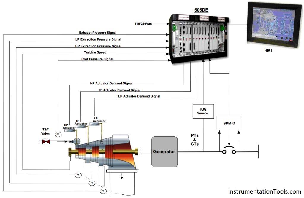
The user has to configure the details of the control requirements which involves selecting the various control modes and entering the details of the inputs and outputs. The Woodward 505 has a alpha-numerical display and an integral keyboard for this task. The newer generation of standard controls will have the configuration done by computers such as PC or laptop.
All the Woodward standard controls are configured by answering questions which appear on the display by entering yes/no answers or entering numerical values.
Standard controls cover the majority of applications of mechanical drives. However, for more complex applications of large turbines having an extensive protection system or more complex applications such as a train of steam turbine/compressor, the requirements do not fit in a standard control and a custom programmed control is needed.
Controls with a standard program usually are less expansive because the application program does not have to be functionally tested for every control.
2. Two Valves Turbines: With two valves, the control can modulate two parameters simultaneously. For power plat, turbines in Generator application, this can be a combination of maintaining constant turbine speed and modulating extraction flow. For a variable speed drive such as Compressor application, the two parameters typically are a variable speed control combined with modulating extraction flow. This type of turbine is called a Single Automatic Extraction (SAE) turbine as it has a single extraction port with controlled extraction flow.
1) Single Automatic Extraction:
Turbines with one extraction port are called Single Extraction turbines. The turbine can have control valves on the HP inlet only in which case the extraction flow is not controlled and flow as well as pressure in the extraction header can vary. However if it is important to control the flow in the extraction header, the turbine shall have two valves, one on the HP inlet and a second LP valve downstream of the extraction port. This type of turbine is a Single Automatic Extraction (SAE) turbine. For the majority of SAE turbines, there is only one HP and one LP valve although the design may involve more than one HP and/or more than one LP valves.
Speed / Power Control:
The turbine can drive a compressor in which the turbine speed must vary with compressor demand through a speed governor with the input from a process controller. Another application is a generator operating parallel with a commercial grid. In that case the speed is constant and the control is designed in such a speed/power mode that amount of power from the generator shall not be fluctuating.
Extraction Control:
The second controller is the extraction controller which must modulate the amount of flow in the extraction header. This flow is determined by the demand from the user.
Decoupling:
The back pressure turbine has a control which modulates the flow in the back pressure header while speed or power is not controlled. The SAE turbine is used in applications where both extraction flow and speed or power needs to be controlled simultaneously.
The modern digital control allows de-coupling of the two control modes by making them independent. De-coupling requires the speed/power controller and the extraction controller both operate the HP and LP valves simultaneously.
Rationing:
All steam to provide power must travel from the HP valve, through the HP turbine, through the LP valve and the LP turbine to turbine exhaust with none of the steam travelling to the extraction port. All steam to satisfy extraction demand must travel from the HP valve, through the HP turbine to the extraction port without any of this steam going through the LP section.
Any change in flow demand in the extraction header requires the pressire controller operates both valve simultaneously. The steam does expand in the HP section on its way to the extraction port and that changes the power level. Therefore he LP valve must move in the opposite direction. An increase in extraction demand requires that the HP valve opens but the P valve close to reduce the power produced by the LP valve in an amount equal to the power increase by the HP section of the turbine.
Induction Turbines:
The turbine has two inlets for steam, a High Pressure (HP) and an Intermediate Pressure (IP) inlet. Many plants such as the ethylene plant depend on the reformer to produce the high pressure steam. During the start a boiler produces the intermediate steam and the induction turbine starts on that source. When the process is well on its way and high pressure is available, the turbine switches to high pressure source. Other induction turbines use all the excess steam available from an intermediate pressure header.
Digital Controls for Large, Base Load Utility Steam Turbines:
Utility power plants are complex arrangements of machinery requiring sophisticated control systems to keep all equipment working in harmony and to keep the overall plant operating at its optimum efficiency. Traditional control system includes control of boilers, burner controls, turbine controls and various sections of the balance of plant control. The operator supervises all these different controls from the central control room. Digital technology offers more integration of control functions and improved operator interface but there shall be additional economic benefits for the justification of replacing existing controls.
There are two separate control issues, determined by the nature of the process to be controlled. These areas are: Plant control, Turbine control.
Major improvements in efficiency can be made by changing the operating mode of the plant with turbine control being an important part of this.
In addition to the improvement of the basic operating efficiency there is a secondary efficiency improvement in the increased availability of the turbine. The controls manufacturer can use digital technology in the design of fault tolerant systems which allow a failure in the control hardware without tripping the turbine. It is a truly fault tolerant control, the operator can make repairs and replaces components while the turbine is operating which vastly improves the availability of the turbine.
Steam Turbine Interfaces
The decision to replace an existing control on a steam turbine with a new digital control is only one aspect in the process. The selection of the proper interface between the new control and the existing steam valve is just as important for the success of the project. The majority of the vintage controls are mechanical or electro-mechanical and the interfaces with the steam valve servo are mechanical linkages or hydraulic pressures. The new electric control has a voltage or current output representing steam demand. For the older turbines this electric signal must now interface with existing mechanical devices which operate the steam valve. Some of the problems with the existing governor, leading to the decision to replace the control may be a combination of governor problems and servo deficiencies. Therefore, the incorrect interface may affect the performance of the turbine-control combination regardless of the improvements from the new electronic control.
Mechanical Input:
Small Turbine may have a mechanical governor or mechanical-hydraulic governor directly operating the steam valve. Larger turbines require more force to operate the valves and these turbines have multiple stage servos. Most basic designs have a single pilot valve which modulates the flow of oil to the power piston which, in turn, operates the steam valve(s). (Governor, pilot valve, power piston, steam valve). Occasionally, very large turbines may have several stages of amplification with two or more pilot valves in series.
Mechanical Trip:
Over speed protection is the primary trip but other trips involving lube oil and other parameters may be involved. Should the existing mechanical trips be maintained and a new electrical trip mechanism be added or should the existing trip mechanism be completely replaced? If the existing mechanical system does not cause nuisance trips, it can be retained as the secondary trip and a new electrical system can be added as primary protection. Insurance regulation may even require that the mechanical trip be retained.
Electric Trip:
The software for the protection can be in the digital turbine control as long as a second, independent, trip is provided for the (very remote) case that there is a failure in the turbine control. More common is to have the overspeed protection as a separate device. The trip valves are dormant all the time and periodic testing is essential to assure that they operate when required. The two isolation valves are added which can isolate one trip valve for testing while the other trip valve remains active. Once the switch on the isolation valve indicates that the trip valve is isolated, the operator can test the trip valve.
Lube Oil Consoles:
Manufacturers manufacture Hydraulic Power Units (HPU) with single and duplex electric motor driven pumps. These are standard designs and provide pressure oil to the electro-hydraulic actuators. Manufacturer also can design custom designed lube oil consoles providing low pressure oil for the turbine and high pressure oil for the servo.
Author : Subodh Kumar Tikadar