What is PLC Ladder diagram?

There are several languages designed for user communication with a PLC, among which ladder diagram is the most popular. Ladder diagram consists of one vertical line found on the left hand side, and lines which branch off to the right. Line on the left is called a “bus bar”, and lines that branch off to the right are instruction lines.

Conditions which lead to instructions positioned at the right edge of a diagram are stored along instruction lines. Logical combination of these conditions determines when and in what way instruction on the right will execute. Basic elements of a relay diagram can be seen in the following picture.

PLC%20Ladder%20diagram

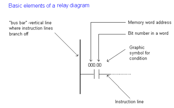
Most instructions require at least one operand, and often more than one. Operand can be some memory location, one memory location bit, or some numeric value -number. In the example above, operand is bit 0 of memory location. In a case when we wish to proclaim a constant as an operand, designation # is used beneath the numeric writing (for a compiler to know it is a constant and not an address.) Based on the picture above, one should note that a ladder diagram consists of two basic parts: left section also called conditional, and a right section which has instructions. When a condition is fulfilled, instruction is executed, and that’s all!

PLC%20Ladder%20diagrams

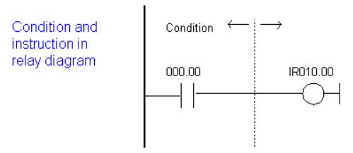
Picture above represents a example of a ladder diagram where relay is activated in PLC controller when signal appears at input line 00. Vertical line pairs are called conditions. Each condition in a ladder diagram has a value ON or OFF, depending on a bit status assigned to it. In this case, this bit is also physically present as an input line (screw terminal) to a PLC controller. If a key is attached to a corresponding screw terminal, you can change bit status from a logic one status to a logic zero status, and vice versa. Status of logic one is usually designated as “ON”, and status of logic zero as “OFF”.

Right section of a ladder diagram is an instruction which is executed if left condition is fulfilled. There are several types of instructions that could easily be divided into simple and complex.

Example of a simple instruction is activation of some bit in memory location. In the example above, this bit has physical connotation because it is connected with a relay inside a PLC controller. When a CPU activates one of the leading four bits in a word IR010, relay contacts move and connect lines attached to it. In this case, these are the lines connected to a screw terminal marked as 00 and to one of COM screw terminals.

1 Like

A PLC (Programmable Logic Controller) ladder diagram is a graphical programming language used for programming PLCs. It is a widely used method for creating and representing control logic in industrial automation systems. The ladder diagram gets its name from its resemblance to a ladder, with horizontal rungs and vertical rails.

PLC ladder diagram

Here are the key features and elements of a PLC ladder diagram:

1. Rungs: A ladder diagram consists of multiple rungs, which are the horizontal lines in the diagram. Each rung represents a specific control function or operation.
2. Contacts: Contacts are graphical symbols used to represent input conditions or sensors. They can be normally open (NO) or normally closed (NC) symbols. Contacts in the ladder diagram are used to represent the status of input devices or conditions that need to be satisfied for the control logic to proceed.
3. Coils: Coils represent output devices or actions to be taken based on the control logic. They can be solenoid valves, motors, or other output devices. Coils in the ladder diagram are energized or de-energized based on the control logic.
4. Power Rails: The two vertical rails in the ladder diagram represent the power supply for the control circuit. The left rail is typically connected to the positive voltage source, and the right rail is connected to the common or ground.
5. Logic Symbols: Ladder diagrams include various logic symbols for implementing control functions. These symbols include AND gates, OR gates, timers, counters, latches, and other specialized functions. They are used to create complex control logic by combining input conditions using logical operators.
6. Branches and Jumps: Ladder diagrams allow for branching and jumping between different rungs or sections of the diagram. Branches and jumps enable more complex control sequences and conditional logic.

By combining the contacts, coils, logic symbols, and power rails in a ladder diagram, the programmer can represent the desired control logic and sequence of operations for a given industrial process or automation system.

Ladder diagrams are popular in industrial automation because they provide a visual representation of the control logic, making it easier to understand and troubleshoot. Additionally, ladder logic programming is based on the familiar concept of electrical control circuits, which makes it accessible to technicians and engineers familiar with electrical wiring and circuitry.