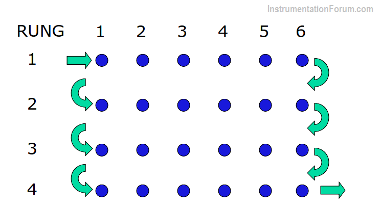
It is important to understand that the input scan, program scan, and output scans are separate, independent functions in PLC.
PLC Scan
Any changes in the status of input devices during the program or output scan are not recognized until the next input scan.
Read these articles on PLC Scan
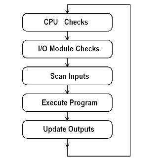
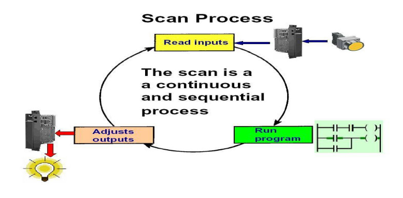
PLCs operate by continually scanning programs and repeat this process many times per second. When a PLC starts, it runs checks on the hardware and software for faults, also called a self-test. If there are no problems, then the PLC will start the scan cycle. The scan cycle consists of three steps: input scan, executing program(s), and output scan.
Input Scan : A simple way of looking at this is the PLC takes a snapshot of the inputs and solves the logic. The PLC looks at each input card to determine if it is ON or OFF and saves this information in a data table for use in the next step. This makes the process faster and avoids cases where an input changes from the start to the end of the program.
Execute Program (or Logic Execution) : The PLC executes a program one instruction at a time using only the memory copy of the inputs the ladder logic program. For example, the program has the first input as ON. Since the PLC knows which inputs are ON/OFF from the previous step, it will be able to decide whether the first output should be turned ON.
Output Scan : When the ladder scan completes, the outputs are updated using the temporary values in memory. The PLC updates the status of the outputs based on which inputs were ON during the first step and the results of executing a program during the second step. The PLC now restarts the process by starting a self-check for faults.
Furthermore, data changes in the output table are not transferred to the output terminals during the input and program scans
The transfer affecting the output devices takes place only during the output scan.
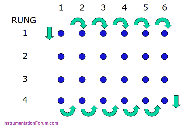
Another scanning consideration involves proper operational sequencing of events.
An output might not go on immediately in sequence as it would in a relay logic system.
In a relay logic system, an event occurring anywhere in the ladder control system results in immediate action.
In a PLC ladder control diagram, however, no effect takes place until the rung is scanned.
In most cases, the PLC logic delay effect is inconsequential.