What is Split Range Control?

Split Range Control is controlled by coordinating the actions of several manipulated variables, all of which have the same effect on the controlled output.

The final alternative to simple feedback control to be discussed in this section is Split-Range Control . This is distinguished by the fact that it has

  • one measurement only (the controlled variable)
  • more than one manipulated variable

The control signal is split into several parts each associated with one of the manipulated variables.

A single process is controlled by coordinating the actions of several manipulated variables, all of which have the same effect on the controlled output.

Split Range Control

Below are described two situations where split-range control is used in chemical processes.

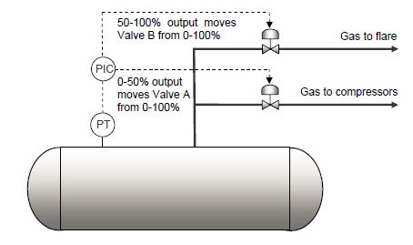
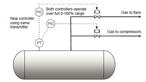
Example 1 - Control of Pressure in a Reactor

The aim of this loop is to control the pressure in the reactor. It may be possible to operate this system with only one of the valves but the second valve is added to provide additional safety and operational optimality.

In this case the action of the two valves should be coordinated. Thus for example if the operating pressure is between 0.5 and 1.5 bar then the control algorithm could be

  • If the pressure is below 0.5 bar then valve 1 is completely open and 2 is completely closed.
  • If the pressure is between 0.5 and 1 bar then valve 1 is completely open while 2 is opened continuously as the pressure rises. Note that both these actions lead to a reduction in pressure.
  • If there is a large increase in pressure and it rises to above 1 bar then valve 2 is completely open while 1 is closed continuously.
  • If the pressure reaches 1.5 bar then valve 1 is shut and 2 is open.

A graph of these valve positions with respect to pressure is shown below.

Example 2 - Control of Pressure in a Steam Header

The aim of this control loop is to maintain a constant pressure in the steam header subject to differing demands for steam further downstream. In this case the signal is split and the steam flow from every boiler is manipulated.

An alternative manipulated variable could be the steam production rate at each boiler via the firing rate. A similar control scheme to the above could be developed for the pressure control of a common discharge or suction header for N parallel compressors.

3 Likes

Split range control is a control strategy in which one tries to control a process parameter (say pressure) by adjusting more than one manipulated variable. in this you may have single controller and more than one final control elements (say control valve. in the case of one controller controls 2 CV,we can do it like this:-

Normal control sognal ranges from 4~20 mA, one can set the zero of 1st control valve as 4mA and 12mA as span of the same, the second one’s zero may be set 12 mA and span 20 mA. in practical the first valve will start open a signal above 4mA and and will be fully open at 12mA after that the Second one starts open and reaches its maximum at 20 mA.

3 Likes

In a split range control loop, output of the controller is split and sent to two or more control valves.

Split range control

A very common control scheme is split range control in which the output of a controller is split to two or more control valves. For example:

  • Controller output 0% Valve A is fully open and Valve B fully closed.

  • Controller output 25% Valve A is 75% open and Valve B 25% open.

  • Controller output 50% Both valves are 50% open.

  • Controller output 75% Valve A is 25% open and Valve B 75% open.

  • Controller output 100% Valve A is fully closed and Valve B fully open.

01

Different arrangements are possible. For example, above figure shows a split range pressure controller on a separator with two valves, one to the flare and one to the compressor suction. In this case, the ‘split’ is configured as follows:

  • Controller output 0% Both valves are closed.

  • Controller output 25% Valve A is 50% open and Valve B still closed.

  • Controller output 50% Valve A is fully open and Valve B closed.

  • Controller output 75% Valve A is fully open and Valve B 50% open.

  • Controller output 100% Both valves are fully open.

The idea is that the suction valve is used for normal pressure control while the flare valve only opens to disperse high pressures.

In this application, the flare valve will need to open quickly in response to high pressures, but the compressor suction valve will need to move much more slowly to prevent instability in the compressors.

The main problem with split range control is that the controller only has one set of tuning parameters. If the controller is tuned to be fast acting to optimize the performance of the flare valve, the suction valve will also move rapidly to produce unstable gas flows to the compressors. If the controller is tuned slower to stabilize the compressors, then the flare valve will not open fast enough as the pressure rises.

A further issue is that the process response of the route to flare generally differs to the process response of the route to the compressors, so both routes will anyway require very different tuning for optimal control.

The solution is to replace the split range controller with two independent controllers, both reading the same pressure transmitter, but one controlling the flare valve and the other the suction valve. Not only can each controller be tuned correctly for its dedicated service, but different set points can also be used to prevent the flare valve from ‘popping’ unnecessarily.

02

The ease with which a split range controller can be replaced with two ordinary controllers depends on a number of factors. If the ‘split’ is calculated in the DCS or PLC so that each valve has its own output from the control system, then the addition of a new controller is simply a matter of software configuration.

However, occasionally, the control system only has one output wired to both controllers and the ‘split’ produced by configuration of the valve positioner. A new output will then be required from the control system to one of the valves and the valve positioners must be reconfigured to operate over the full 0-100% output range.

2 Likes