This motor derives its name from the fact that it can run on either alternating current or direct current . Alternating current is current in which the direction of flow is reversed at regular intervals. Direct current always flows in the same direction.
The value of the universal motor lies in its ability to provide an extremely high starting torque and to attain high speed quickly while under a fairly heavy load. Large list of appliances use the universal motor, and you can see that each of them may require a high torque value and may be asked to operate under heavy loads.
Torque, incidentally, is the tendency of an object to rotate. It is a measure of turning or twisting effort imparted, for our purposes, by a motor.
The AC-DC universal motor consists of two major components: a rotor and stator. Let’s talk about the rotor first.
The rotor is a part that rotates. It doesn’t move up and down, in and out, side to side, or in any other direction than around.
In effect, the rotor of an AC-DC universal motor is made up of an armature, which is an iron core with coils of wire wrapped around it, and the commutator. The commutator and armature are together-that is, they comprise a single assembly (Figure 1).
The commutator, which is positioned on one end of the armature,consists of a series of copper bars laid out in circular fashion. They do not touch each other. Rather, they are insulated from each other by sheets of mica. The commutator is a switching mechanism but more about that in a minute.
Passing right through the middle of the armature and commutator is a shaft that sticks out of both ends. The distance that the shaft extends from each end varies from appliance to appliance, or whatever, and is really not very important.
However, what is important is that one end of the shaft is normally attached to a bearing assembly so the rotor can rotate. (But it doesn’t have to be. In some cases, for example, the shaft may have a small fan that cools the interior of the appliance.) The other end of the shaft is attached to the appliance’s working device. In the case of a food blender, for example, the end of the shaft is attached to the cutting knives.
But that “working” end of the shaft may instead be attached to a gear train which, in turn, is attached to a working element. This is true with food mixers and floor polishers.
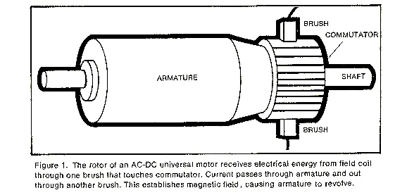
Figure 1. The rotor of an AC-DC universal motor receives electrical energy from field coil through one brush that touches commutator . Current passes through armature and out through another brush.This establishes magnetic field, causing armature to revolve.
Now, what about the stator? Well, that’s the part of the motor in which the rotor is positioned, but keep in mind that it is positioned in this way so its movement cannot be impeded. The stator is a frame (iron, usually) containing coils (wires) called field coils.
Essentially, this is what happens:
electricity enters one of the field coils through the appliance’s line cord, which is plugged into a wall socket. Current passes from the field coil into one of two carbon segments, called brushes, which are positioned directly opposite one another on the commutator. The brushes are held in contact with the commutator by springs.
Okay, current flows through the brush to the one commutator bar the brush is touching, through the armature coil to which the armature is connected, out through another commutator bar that is in contact with the other brush, into another field coil, and back to its source (Figure 2). This means that the brushes and commutator bars, as indicated before, act as an automatic switching device that connects and disconnects each coil at exactly the right moment as the armature revolves.
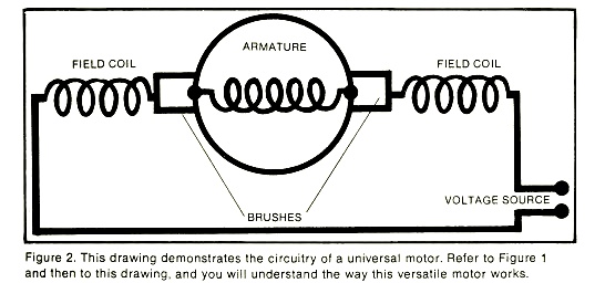
Figure 2. This drawing demonstrates the circuitry of a universal motor. Refer to Figure 1 and then to this drawing, and you will understand the way this versatile motor works.
All components of a universal motor are wired together in tandem, and current at every point is the same. This arrangement is called a series circuit (Figure 3).
This differs from a parallel circuit,which is a term you’ll run across again. In a parallel circuit (which is also called a multiple or shunt circuit), components are arranged so the current divides itself between them (Figure 4).
It is interesting to note that every universal motor is made the same way the smallest and the biggest. Thus, the starter motor in your car, which is a universal motor, has the same configuration and parts as the universal motor in your vacuum cleaner.
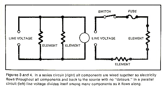
Figures 3 and 4. In a series circuit (right) all components are wired together so electricity flows throughout all components and back to the source with no “detours .” In a parallel circuit (left) line voltage divides itself among many components as it flows along.