While analizing the process that you have to automate you always have many conditions to respect for the safeness of the equipments, of the operators and of the process itself.
What is an Alarm
An alarm is a condition of non-safe state of the machine.
Depending on the impact on the process, it can be:
- Blocking
- Not blocking
An alarm can be connected to an input sensor, but it’s never the sensor itself; alarms are generally stored in words (16-bits registers) and displayed in the HMI, as well as used in the program as conditions to grant the safeness of the process.
What is interlocked equipment
Interlocked equipment, like motors or valves, is an equipment that has a protection circuit (real or logic) that interdicts the activation of the equipment if at least one danger condition is met.
Alarms with ladder logic
When i write alarms and interlocks i always use the same structure, that consists in many words where every bit corresponds to an alarm; this structure is almost a standard for many operators panel and has many good points but some drawbacks too (a drawback is that you can analize block of alarms comparing and masking entire words, that can be cheaper to write, but harder to understand when reading or debugging).
This is a basic sample on how i write an alarm block:
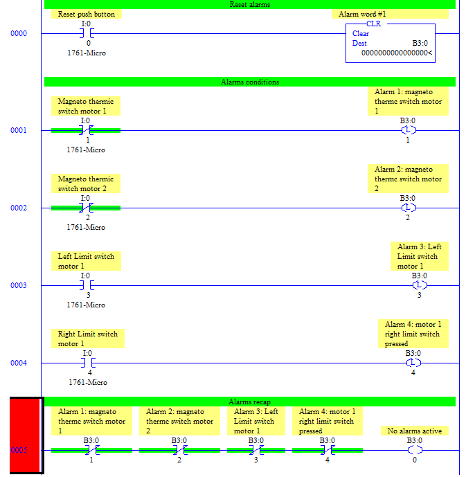
When writing alarms in this way the first segment must be always the reset block. This because even if you reset all the alarms pushing the reset button, if one fault condition is active, the alarm will be setted again few segments later, resulting in a still active alarm at the end of the program.
The last part is a recap of all alarms, really useful while debuggin because you can notice instantly what’s going on just by watching 1 segment.
The first bit of the word alarm has been chosen as “no active alarms” because usually:
- Alarms starts from number 1 and continues, so it’s no use to have an offset among alarms and bits
- This bits triggers all the alarms-screens and alerts on HMI and scada.
Writing interlocked equipment in ladder logic:
Once you detected the fault conditions for your plant, you should use alarms and other conditions inside interlocks to avoid dangerous operations.
I usually write outputs logic and interlocks in this way:
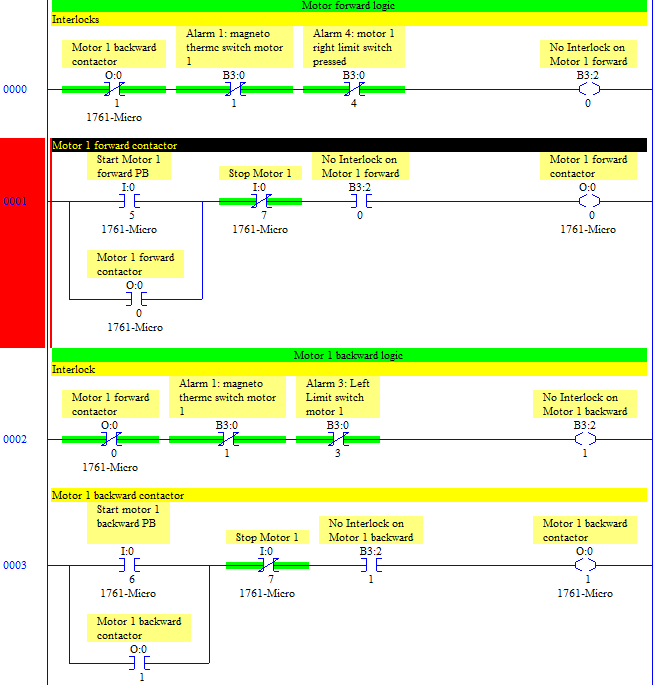
Same as alarms, interlocks must be above the segment that declares the output coil condition and the interlock bit should include every condition that stops the motor.
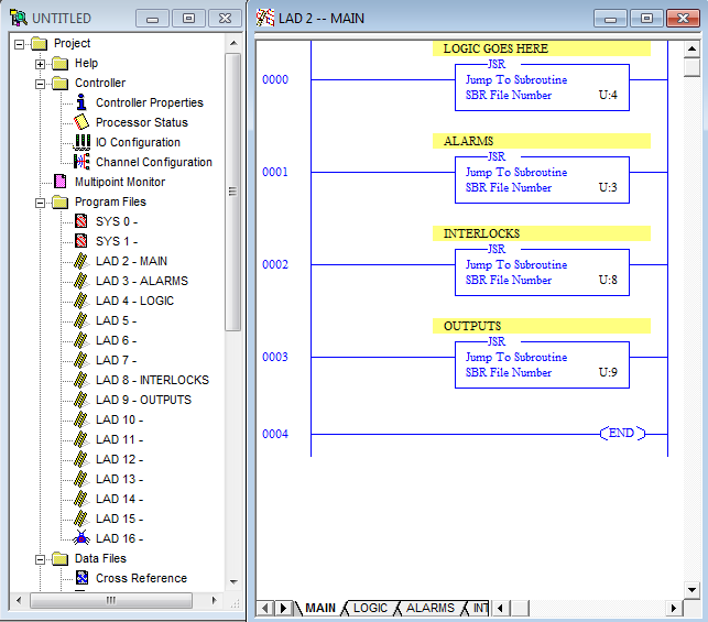
A common strategy that peoples uses when outputs grows in number is to have a block dedicated to interlocks that comes exactly before the block dedicated to output, like this:
credits- Mesta Automation