The axial type turbine flow meter consists of a circular housing with a suspended blade system. This suspended blade is mounted on a shaft or bearing at the center of the housing. As fluid flows past the blades, they are rotated by the fluidic forces. The speed of rotation is proportional to the velocity of the fluid passing through the housing.
A method of measuring the speed of rotation is employed, allowing a measurement of fluid velocity. The typical method if measuring the speed of the turbine rotation is to count the blades as they pass a sensor on housing body. This method is extremely accurate and essentially averages the velocity across the whole housing diameter.
The construction of these devices can allow insertion into pipes and ducts of varying sizes and can be used with a wide variety of clean fluids over a very wide range of velocities. The design of the housing can be adjusted to allow the use of this type of transducer into a wide range of pressure systems.
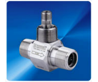
These systems frequently apply a flow straightener section immediately prior to the blade section. The Blancett model 1100 is typical of this type of flow meter.
This style flow meter is available in a wide array of sizes and velocity ranges, but is inherently limited to flows that can be totally encapsulated by the body. In large diameter ducts or pipes this type meter becomes impractical due to the extreme velocities that the tips of the blades would be subjected to as the diameters grow.
This type of flow meter has excellent accuracy in both liquids and medium velocity gasses. Since the accuracy of the meter depends on the speed of the impeller, it is imperative that the bearing system that supports the blade remain clean and free to turn. This tends to limit the fluids to “clean” fluids that do not contain significant numbers of abrasive particles.
Many installations install 100µ filters upstream of the meter to ensure that the fluid flow does not contain damaging particles. An additional consideration with is the issue of wetted parts. Since the blades and bearing are fully immersed in the fluid, care must be taken to assure that the materials that the meter is made from are compatible with the fluid being measured.
Highly corrosive fluids and gasses can have a significant impact on the life of the meter. Additionally these meters are usable with a wide range of viscosities, although certain calibration corrections may need to be applied, depending on the meter, since the amount of “slip” between the fluid and the blade is a factor in its calibration.
As the blades rotate, a mechanism is employed to count the passing of the tips of the blades. In general a magnetic field is induced into the flow field and the disturbance of this field creates a pulse output from the meter. Counting these pulses or measuring the rate of their passage will allow for measurement of flow. Since the meter depends on the magnetic field for operation, it is clear that fluids that effect magnetic fields should be used cautiously with this type of meter.
Credits - Mitchell Cottrell