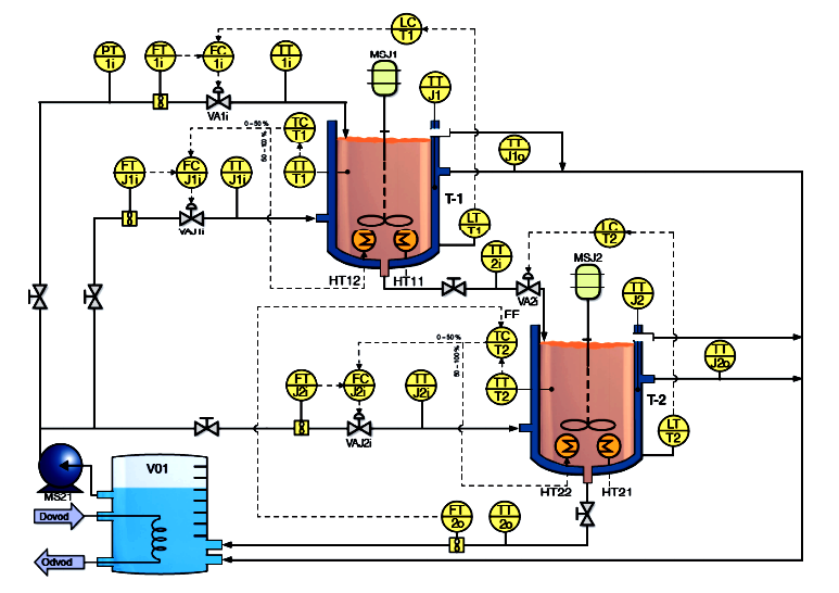
The P&ID is used by field technicians, engineers and operators to better understand the process and how the instrumentation is interconnected.
Graphical description of the process and process equipment Graphical description of the process and process equipment using standard symbols (ANSI/ISA-S5.1 Instrumentation Symbols and Identification).
• Includes more details than a PFD;
• Major and minor flows, control loops and instrumentation;
• It shows the process flow, measuring sensors, transducers and final control elements and devices.
On P & I diagrams we can find pipes, pneumatic/hydraulic elements, electrical elements, instruments and process equipment
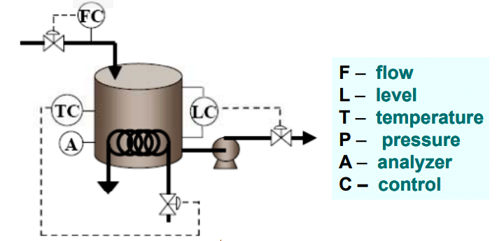
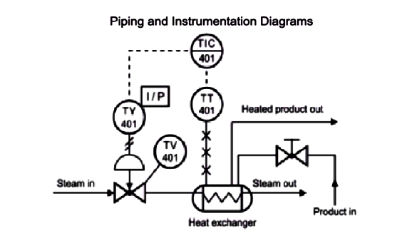
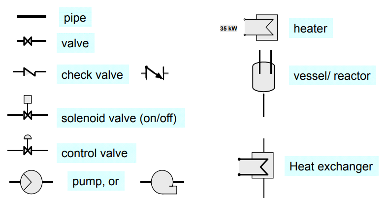
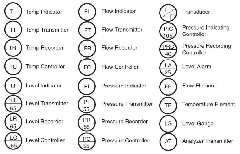
Examples of symbols:
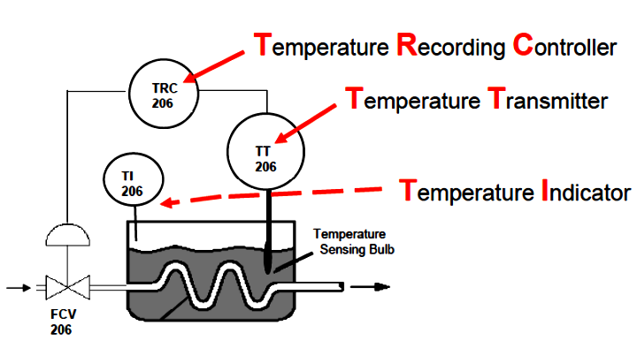
Tag Numbers
Tag “numbers” are letters and numbers placed within or near the instrument to identify the type and function of the device.
Tag Descriptors
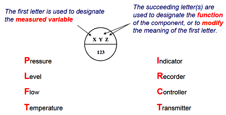
ISA S5.1 IDENTIFICATION IDENTIFICATION LETTERS
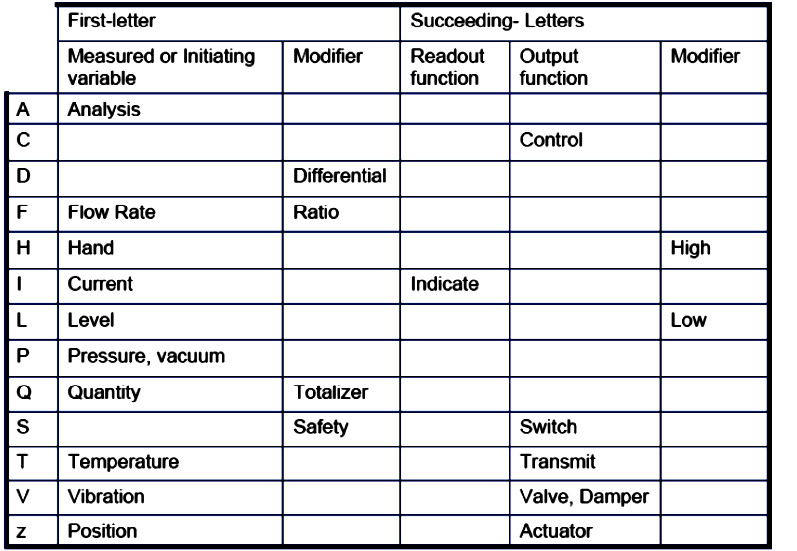
Tag Descriptors
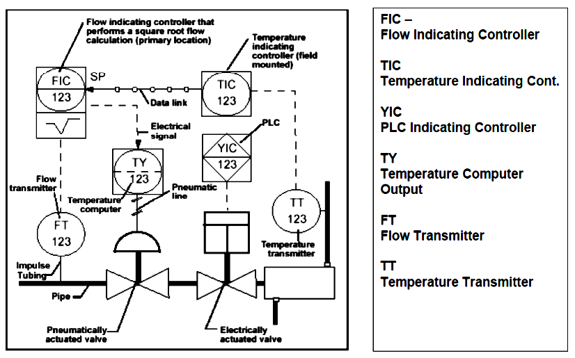
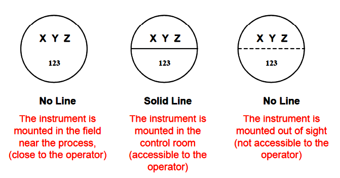
Instrument Location
The presence or absence of a line determines the location of the physical device;
For example no line means the instrument is installed in the field near the process field near the process.
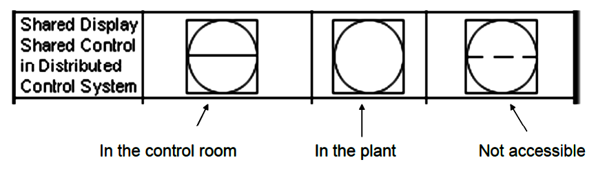
Shared Displays / Shared Control
Some instruments are part of a Distributed Control System (DCS) where a specific controller or indicator can be selected from many others but shown in one location (like a terminal screen ).
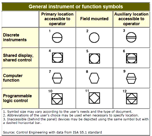
Instrument Type and Location
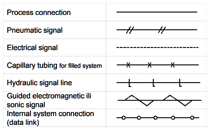
Piping and Connection Symbols
Used to identify how the instruments in the process connect to each other and hat type of signal is being used.