The ISA and IEC standards defined a safety-instrumented system as “a system composed of sensors, logic solvers, and final control elements for the purpose of talking the process to a safe state, when predetermined conditions are violated”.
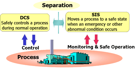
Basics of Safety Instrumented Systems (SIS)
In a nutshell, an SIS is an automatic system designed to perform one or more of the following functions:
a) protection against situations that endanger the health or lives of plant personnel
b) protection against situations that results in the risk of equipment damage
c) protection against fire and/or explosion
Basic Configuration of an SIS
The basic components of an SIS can be shown schematically
These are the sensors with associated signal transmission and power, logic solver with power supply, input and output signal processing, actuators and switching devices to execute the final elements. For an example of a typical features of an SIS.
The components are briefly discussed below:
-
Sensors are used to measure process variables such as temperature, pressure, flow, level, etc. They may consists of simple pneumatic or electric switches, which change state when a set point is reached, or they may contain pneumatic or electronic analog transmitters, which give a variable output in relation to the strength or level of the process variable.
-
A logic solver component (such as relays or programmable logic controllers) that receives the output signal from one or more alarm switches or transmitters and then decides, based on pre-planned logic, what output or outputs should be sent to an annunciator and any final devices that are to be automatically activated. This is commonly known as the interlocks system.
-
An annunciator, possibly with a final device or devices that will produce appropriate action in response to outputs from the logic solver.
-
A final device causes an automatic shutdown of operating equipment. Common types of final devices include:
-
An electric relay acting as a “stop” or “start” button in the control circuit of the starter for an electric motor.
-
A solenoid-operated emergency valve.
-
A solenoid-operated pilot valve, which can load or vent air pressure from a spring/diaphragm actuator on an emergency valve.
-
A motorized valve, damper, or gate. These are not as practical as the first 3 because they have no fail-safe position. Power is required to drive them to their safe status. If the emergency involves loss of power, then motorized devices cannot respond.