A simplified system to control the temperature of a process employing a gas burner using two Cascade Control digital controllers is shown in Fig. 21.21.
Each controller has a number of digital inputs and outputs, and also a number of and outputs, the actual inputs and outputs are limited to those used to control the system, although the inputs and outputs are also available to the user in a practical system.
In the case of the master controller, the remote set points enable input which is a digital input. If the controller has a logic 0 applied to it, this disables the analog ‘remote set point’ input of the master controller. The temperature of the process being controlled is sensed by a Thermocouple (TC). This signal, after amplification, is applied to the process variable analog input of the controller.
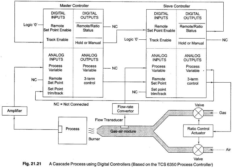
This signal is compared with the set point of the master controller, and the resulting deviation produces an output at the analog 3-term output.
This signal becomes the analog remote set point of the slave controller (The remote set point of the slave controller is enabled by the digital ‘remote / ratio’ status terminal of the master controller), hence the master controller controls the set point of the slave. The analog 3-term control output signal of the slave controller changes the relative rates of the flow of air and gas via a ratio controller which could also be a digital controller. A signal proportional to the flow rate of the air-gas mixture is used as the analog process variable input of the slave controller.
A copy of this signal appears at the process variable output terminal and is used as a track signal for the master controller. This ensures that, during start up, the 3-term output of the master is forced to follow the process variable signal of the slave, so that the remote set point of the slave is equal to its own process variable signal. The object of this arrangement is to ensure a bumpless’ transfer from any operating mode into cascade. The track operation of the master controller is enabled by a logic signal applied to thetrack’ enable digital input of the master controller.
As the temperature of the process varies, the master controller causes the slave controller to alter the flow rate of the air-gas mixture to result in a stable operating temperature.