Instrumentation and control design engineers add all the loop and local instruments to the
P&ID, to define the instrumentation and control scheme.
Control Loop
Let’s take a problem statement of controlling flow rate in the pipeline.
Figure below shows an electronic loop consisting of a flow control element (orifice plate), flow
transmitter, controller, transducer and a fail open control valve.
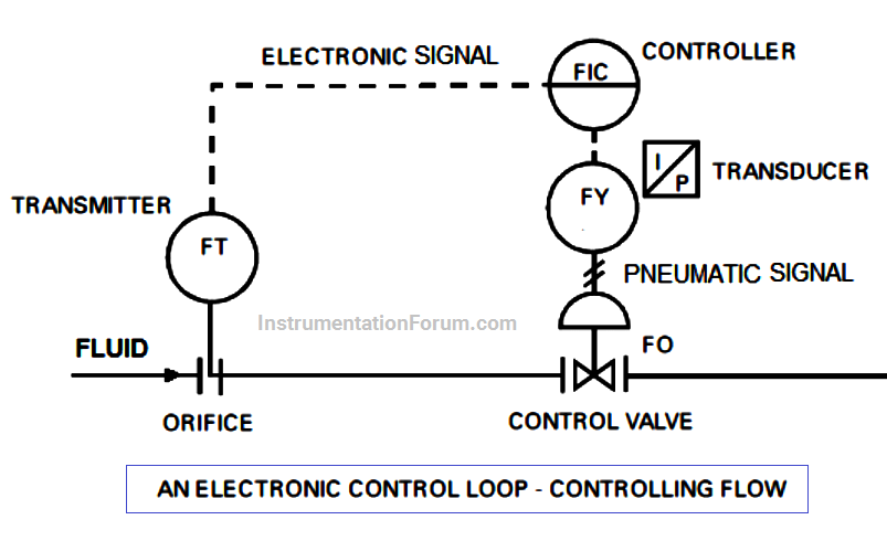
• FT (Flow transmitter) senses the differential pressure proportional to the flow rate in the line caused by a flow element or orifice plate and transmits a 4-20 mA dc (direct current) signal corresponding to the varying differential pressure.
• FIC (Electronic flow controller) transmits a 4-20 mA dc signal to the converter or transducer, FY.
• FY (Transducer) converts the 4-20 mA DC signal into a pneumatic signal. This signal changes the position of the valve actuator, which in turn changes the position of the control valve trim causing change in flow through the control valve.
The dotted line indicates that information is transmitted electronically from the flow transmitter, FT, to the controller, FIC, and from the controller to pneumatic converter (I/P), FY. Simple instruments permit direct reading of a process variable in the field. These devices include pressure gauges, thermometers, level gauges and rotameters.
Other loops are slightly more complex, transmitting a signal to the remote control room, where the measurements can be read or recorded.