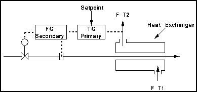
Control of a Heat Exchanger

Components
- A Temperature Indicator
- A Flow Indicator - Orifice Meter
- A Control Valve
- A Temperature Controller
- A Flow Controller
Strategy
This shows a typical cascade control scheme of a heat exchanger. The aim is to keep T2 as close to the setpoint as possible.
- Measured variables
- flow of material inside tubes
- temperature of material in shell
- Manipulated variable - flow of material in tube
- Disturbances
- flow through shell
- flow through tubes
- temperature through tubes
- change in temperature T1
Operation
An increase in T2 can be caused by
- Increase in T1
- Decrease in F
- Increase in temp through tubes
- Decrease in flow through tubes - assume that it is cooling water in tubes
To compensate the flow through the tubes should be increased. However, there is a second loop which compensates for changes in the flowrate.
The TC (Primary Loop) detects changes in the temperature brought about by changes in T1 , F or the temperature in the tubes. The FC (Secondary Loop) detects changes in the cooling water flow and hence eliminates anticipated effects on the temperature T2 .