The pneumatic-assisted control valves require a converter to change the proportional electrical signal to a proportional pneumatic signal. In this figure, the converter is shown as part of the valve. In some cases the converter is a separate part mounted near the valve. The converter is generally mounted in a location where it can be serviced easily and the valve is generally mounted in the piping.
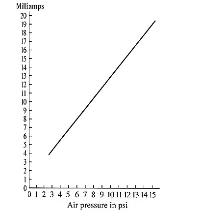
The proportional electrical signal is generally a 4-20 mA current signal, and the air pressure signal is generally set for 3-15 psi. This type of signal converter is called an I/P converter because it changes a current signal (I) to a pressure signal (P).
Below figure shows an example of an I/P converter. It uses a magnetic coil to change the position of a balance beam that controls a small amount of pilot air pressure. The pilot air pressure controls the main air pressure that’s regulated at 3-15 psi. The air supply for the I/P converter must be approximately 20 psi so that the converter can control the pressure between 3-15 psi.
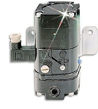
This device has an air pressure gauge to indicate the supply air, and another gauge to indicate the regulated pressure.
For example, when the electrical signal is at its minimum (4 mA), the air pressure signal will also be at its minimum (3 psi). When the electrical signal is at its maximum (20 mA), the air pressure signal will be at its maximum (15 psi). The midpoint value for the electrical signal is 12 mA, which provides 9 psi.
Also Check -