Very few plants have one monolithic controller running everything. Instead, many have subsystems that need to be interconnected for maximum effectiveness.
Integrating multiple control systems
When considering the control system running a process unit or an entire plant, it’s easy to picture it as a single thing, one distributed control system (DCS), controlling everything.
Although there is probably a DCS or large-scale programmable logic controller (PLC)/programmable automation controller (PAC) controlling the process, there are additional control systems running smaller operations within the facility, process units, and auxiliary systems.
This kind of approach has been in use for a long time. After all, the “D” in DCS stands for distributed, which suggests control functions spread out with a high degree of autonomy but tied back to one, central place.
In fact, there can be quite a few autonomous control functions, depending on the nature and overall complexity of the process itself. For example, here are a few processes and systems, each which might be monitored by the DCS but have independent control mechanisms:
- · Hot water
- · Chilled water
- · Steam
- · Fired heaters
- · Power distribution
- · Analyzers
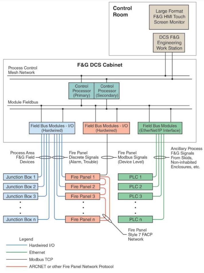
- · Fire and gas detection systems
- · Skidded equipment (chemical injection, incinerators, etc.)
- · Communications
- · Water supplies (soft, filtered, reverse osmosis, water for injection)
- · Clean-in-place systems
- · HVAC
- · Wastewater
- · Compressed air
- · Refrigeration
- · Environmental
- · Emergency power.
Theoretically, one DCS could control any of these, and it is possible to control every aspect of a plant from a central point.
However, in most plants it isn’t practical and would cause unnecessary complexity. Safety instrumented systems (SISs) would be the first thing off the list because they function independently. Similar functional considerations also influence other decisions.
Functionality
Some decisions of when to break free of the DCS are based on functionality. A DCS is, at its heart, an analog system.
It is designed to support control loops driven by sensors with scalar, analog output, and control scalar, analog actuated devices. It can work with discrete devices and functions, but they are not its best application.
For the purposes of this discussion, discrete means a device with simple on/off functionality such as a motor starter, pressure switch, or quarter-turn valve.
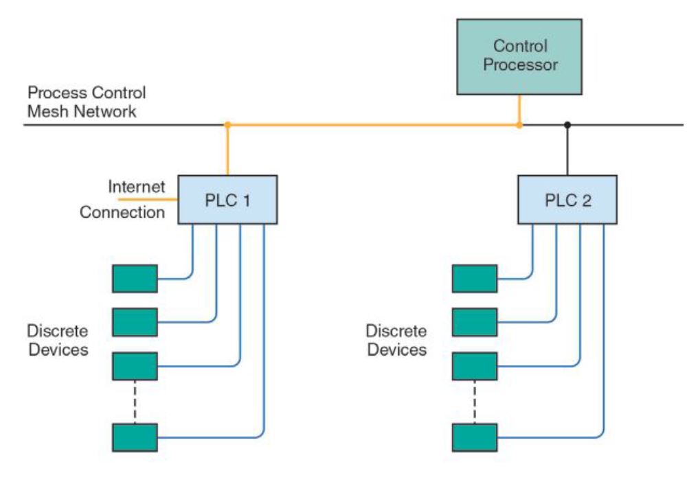
Process units have many discrete control functions. Pumps have to be turned on and off, alarms may need to be activated, and so on.
A DCS could handle those, but when there are many related things which must work together, it’s best to split them off and control them with one or more PLCs or other controllers more suited for those operations. Supplementary PLCs can communicate with the DCS while controlling these local functions.
Operators in the control room will need to know what the secondary systems are doing, so the function will be incorporated into the normal control graphics, but the DCS will only be passing information and commands without performing any real time control itself.
Safety and regulatory choices
As mentioned earlier, safety functions and systems are separated from the DCS. These fall under various regulations, but the common denominator is the need for independent functionality.
If a system needs to shut down some part of the unit and move to a safe state, for example when pressure in a reactor exceeds a set limit, it must be able to execute the function regardless of what the DCS is doing and without human intervention.
In some cases, a safety function may depend on something as basic as a pressure switch sending a signal to a logic solver controlling a relief valve. The logic solver can open the valve without any assistance from the DCS or operator. It will probably send a signal to the DCS saying it has done its task and trigger an alarm, but the communication is strictly one way.
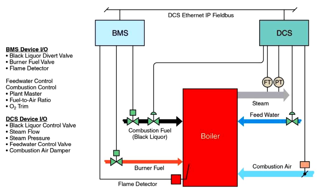
As a more complex example, a paper mill has a recovery boiler system to support the paper making process and supply steam to turbines used to generate electricity, sending the exhaust to heat paper drying rollers.
The boiler has two main functional systems: combustion control to determine how much steam it’s putting out, plus a burner management system (BMS) to ensure it is running properly with a stable flame and no residual unburned fuel. In this case, the primary fuel is black liquor supported by fuel oil or gas.
Since steam output is a process variable based on the needs of the paper machine and the amount of power the generators are producing, it is controlled by the DCS. It tells the boiler how much steam to put out, and it does it by controlling fuel flow (black liquor) and combustion air for the necessary amount of fired heat, along with feedwater to keep up with steam output.
The BMS, on the other hand, is a more discrete function. It turns the fuel on and off. If there is a problem, it shuts down. It needs to be able to execute such a shutdown even if the DCS is calling for steam. The BMS is governed by a variety of safety regulations, including National Fire Protection Association (NFPA) regulations, which define how it has to function.
Communication method fit for purpose
All of the subsystems have to be tied together so operators can monitor and control all the elements from one place. Even if a chemical injection skid is fully capable of working on its own, operators will want to be able to turn it on and off and know what its settings are without having to hike out to wherever it is. Nothing exists in total isolation.
The nature of the inter-system connections depends on the functionality and speed. If there is a strong safety element, the subsystem will probably be hardwired, I/O to I/O.
Something less critical can communicate via Modbus or some other serial network, or increasingly, via an Ethernet protocol. Direct serial links are being replaced by more conventional Ethernet networking strategies as IT practices move onto the plant floor.
Larger networks are particularly useful where a subsystem has to connect to multiple DCS platforms, such as where a plant utility might have to serve more than one process unit. The subsystem has to be sophisticated enough to balance those demands and adjust itself accordingly.
Cybersecurity
As networks grow in size and complexity, the attack surface for intrusions by criminals also grows. Adding a pump skid with its own small control system does not have to create another entry point, but it certainly can do so, often with good reason.
Say the pump skid builder realizes it may be necessary to access the skid at some future point to gather diagnostic information or troubleshoot a problem.
The engineer adds a cellular modem or a Wi-Fi router to the control cabinet so the technician can access the device. This connectivity was not specified by the customer— the builder did it for its own convenience. If a hacker can access this device, it can serve as an entry to the larger system. The customer needs to be very specific as to what communication capabilities are permissible and which are definitely not.
When multiple systems are connected by a network, appropriate isolation and segmentation should be observed. For example, say someone within the company decides it is important to monitor the performance of a skidded subsystem for whatever reason. The individual might ask for access to the desired data via the DCS.
As control strategies continue to evolve, the practice of separating small functional areas from a larger overarching system to create truly distributed control systems will continue.
As networking gets easier, so do the mechanics of connecting these distributed systems in a far more modular fashion.
This coincides with higher intelligence at the device level, permitting more components to think and act for themselves without the need for a large central processor to carry out calculations.