Although relay logic has been replaced by modern electronic devices, it’s still now used on old elevators.
The image below shows a basic relay logic (designed for educational purpose) of a traction elevator with manual doors.
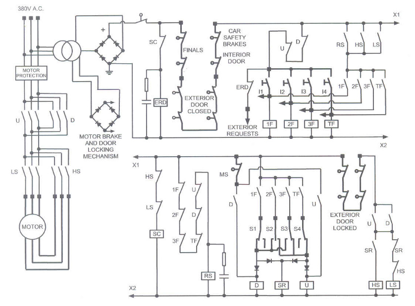
Schematic description
ERD - exterior requests relay (delay off)
I1, I2, I3, I4 - interior requests buttons
RS - reset relay
D, U - motor direction contactors
SR - speed control relay
HS, LS - motor speed contactors
S1, S2, S3, S4 - direction selectors, fixed in the shaft and turned by a rail fixed on the car.
MS - stop magnetic switch
Basically an elevator panel consists of a power circuit, which supplies the motor, and a low voltage control circuit: this one supplies the relay coils, the motor brake and the doors locking mechanism.
At the head of the control circuit there are the safety switches.
The automatic switch cuts off the relay circuit if an insulation failure occurs (for example between the doors safety circuit and the ground); that would be dangerous because the elevator may move with open doors.
Also Download: Elevator Logic.pdf (646.0 KB)
The interlock allows the requests when the door is closed. However the motion of the elevator is allowed by a second switch, when the door is locked.
The finals work if the elevator goes over an extreme floor (due to a motor brake failure, for example).
The car safety brake is a mechanical device that prevents the elevator from falling; it works in combination with the governor.
Warning: This is not an expert guide. Do not access electric and mechanical part of elevators if you are not an expert.
Author: Andrea