There are different industrial communication protocols, the traditional 4-20 mA, HART, Fieldbus, Profibus. HART is one of the most popular communication protocols because its low cost and the reliability.
Traditional 4 -20mA control signal
The traditional 4-20mA control signal is the most used analog signal in the industry, because its low cost in comparison with other communication protocols, the reliability and is easy to install. The range 4 -20mA represents the 0-100% of the range transmitted.
To detect a device failure, this analog signal uses the saturation values, depending of the saturation value configured on the transmitter that could be high (above 20 mA) or low (below 4mA).
This analog communication uses the 4mA as its lower value because this is enough current to calibrate a transmitter when the process variable is zero.
Why use the current signal instead the voltage signal?
The answer is simple, if we have a long distance wiring, the voltage signal presents loss of voltage, while the current signal keeps constant the current through the cable.
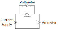
What can we do if the device in the field is dived by voltage and we have a current 4 to 20 mA control signal?
This is not a common scenario, but with a simple circuit we can do the conversion from current to voltage:
But the 4-20 mA signal has a disadvantage respect the other industrial communication protocols, it doesn’t give the status (diagnostics) of the device. That why the HART communication starts taking popularity, because combines the advantages of the signal 4-20 mA but also provides the digital signal with the status of the device.
HART Communication Protocol
The HART signal combines the reliability of the 4 -20 mA signal and give access to the configuration and diagnostic of the field device through a digital signal overlapping on the analog signal. The digital signal generates a “0” or “1” depending if the signal frequency is 2200 Hz or 1100 Hz respectively as shows in the following picture:
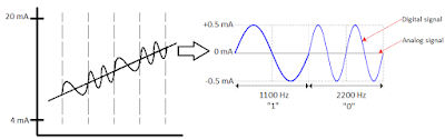
HART signal, frequency and amplitude
The HART communication loop requires a minimum resistance of 250Ω to recognize the signal by the control system or the HART communicator.
The HART device converts the analog signal coming from the transducer to a digital signal, this is done by the A/D converter. The A/D converter takes samples of the analog signals and convert each sample to the closest digital value. there are two factors that can affect the conversion of the signal. The first factor is the rate of sample , meaning the number of times per second that the converter sampled the analog signal. The second factor is the sample precision , this is the smallest change on the analog signal that can be detected by the A/D converter.
Then the sampled digital signal is passed to a signal processor to get a more accurate value. The signal processor also generates the HART digital signal that overlays the analog output signal. The sampled signal is passed to a D/A converter (Digital to Analog converter). This D/A converter produces an analog signal based on the sampled signals.
The control systems could continue using the analog 4 -20 mA for control, because its reliability, and the digital signal is mostly used to generate alerts about the status of the device, calibration and configuration. It is not recommended to use the digital signal to control valves, pumps, motors, etc. When there is a multivariable device, it is recommended to configure the signal that is going to be used for the control as the primary process value with analog communication 4 – 20 mA, this configuration can be made on the device. The rest of the signals could be received by HART communication.
The configuration or calibration can be made by programs installed on the workstations of the control network, these programs allow the communication between the HART device and the system. Also, you can use a HART handheld or HART field communicator to calibrate or configure the device.
You can connect the HART communicators anywhere in the loop, the only requirement is the minimum resistance of 250Ω in parallel to the communicator.
There are a lot if HART device manufactures around the world, to allow the communication of the HART device to the control system or HART field communicator, it is required a “driver” of the HART device known as “device description file”. If the control system doesn’t have installed this device description file, it can still communicate with the device, but is going to receive just the analog 4 – 20 mA signal and the digital signal will be lost. Also, the control system, like a PLC, DCS must have an IO HART card in order to receive the HART signal from the field device.
Devices from the same manufacture and same device type and revision, only require one installation of the device descriptor file, if the revision change, then you will need a new device descriptor file. The manufacturers provide this files in their websites, it is recommendable to download this file from a trusted source to avoid malware.
The HART transmitters could be 2 wire or 4 wire connection. When the connection is 2 wire, the transmitter is powered by the I/O card. When the connection is 4 wire, the transmitter is powered by an external power supply.
These are just a few examples of the functionalities we could have from HART devices:
The HART transmitters could have more than one variable, for example, a flow transmitter can send not just the flow, it also transmits the density and the temperature of the fluid. So you can configure the device to send the signals you are interested and reference the correct signal on the control system.
The HART control valves with positioner, not only receive the 4 to 20mA to open or close the valve, the positioner also transmit the feedback or the actual position of the valve.
The safety shutoff valves in normal conditions are valves that you don’t have to move unless a safety trip occurs. In order to avoid the valve gets stuck due the lack of use, you can configure periodic partial stroke tests. The HART communication of the valve allows you to execute the partial stroke test, defining the percentage that you want to move the valve without representing a danger to the process and the time the valve will stay in this percentage before it comes back to the original position.
The HART transmitters generates alerts about the conditions of the transmitter, for example, we have temperature transmitter with dual sensor, if the primary sensor fails, the secondary sensor or the hot backup sensor takes place, and the transmitter send you an alert about the primary sensor failure.