The documents which represents installation standards is called hook-up drawings.
With hook-up drawings, an engineer can understand how an instrument to be installed in the plant. With hook up drawing we can calculate the material requirement.
Two types of hook up drawings are there.
Pneumatic hookup.
It is independent of process connection. Pneumatic hookup is basically Tubing/piping
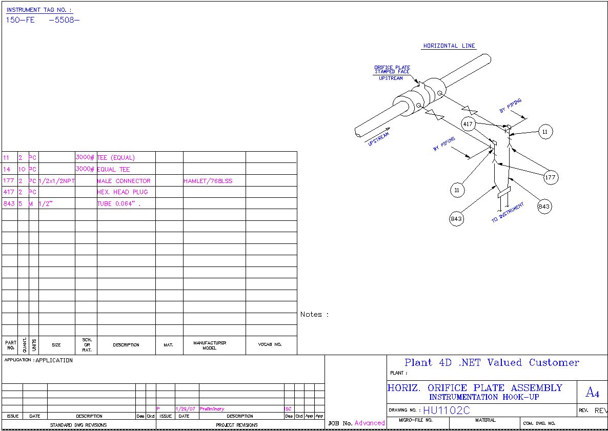
Process hookup.
Here instruments are directly connected to process line.
Instrument hook-up drawings are detailed diagrams or schematics used in the field of instrumentation that show how an instrument is to be installed and connected with other instruments or devices in a system. They provide a guide for engineers and technicians to properly install and connect instruments in a safe and efficient manner.
Instrument hook-up drawing
Here’s what you need to know about them:
Components: Hook-up drawings typically include details about the various components involved in the installation, such as the instrument, process and pneumatic connections, tubing and fittings, isolation and bypass valves, and mounting accessories.
Connections: The drawings show how each instrument is connected to the process line and to the control system. This includes details about the type of connection (e.g., flanged, threaded, welded), the size and rating of the connection, and the type of signal being transmitted (e.g., pneumatic, electric, digital).
Installation Details: They provide information about how the instrument should be mounted (e.g., on a pipe, on a wall, on a stand), the orientation of the instrument, and any special installation requirements.
Bill of Materials: Hook-up drawings often include a bill of materials that lists all the components and materials required for the installation.
Standards and Codes: The drawings should comply with relevant industry standards and codes, which ensure the safety and reliability of the instrument installation.
Purpose: The main purpose of hook-up drawings is to provide clear and accurate instructions for the installation of instruments. They help to ensure that instruments are installed correctly, which is crucial for the accurate measurement and control of process variables.
Usage: These drawings are used by various professionals, including instrument engineers, control system engineers, and technicians. They are often part of the documentation package for a project and are used during the construction and commissioning phases.
The exact details included in a hook-up drawing can vary depending on the specific instrument and application. Always refer to the manufacturer’s documentation and consult with a qualified engineer if you have any questions about a particular instrument installation.