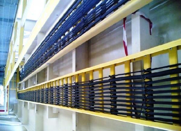
All cables should be installed in one unbroken length between two termination points. For optimum cable usage and to prevent wastage, a cable drum and cable number take-off schedule is prepared. .
Instrument cables are generally not clamped/supported to equipment, process piping, handrails, structural steel etc.

Near the instrument, a cable slack of at least 0.5 m shall be provided, to facilitate termination/disconnection. This portion of the cable shall be protected against mechanical damage by a flexible metal conduit if the cable is unarmored.
In order to prevent galvanic corrosion, direct contact of trunking, trays, supports etc. to non-ferrous metal shall be avoided by applying proper insulating methods.
Cables connected to instruments which have the possibility of an internal release of flammable medium shall be provided with a sealing fitting to prevent liquid/gas transport.
Cable manufacturers’ specifications shall be followed with respect to the minimum bending radius and pulling strength of the cables.
Cables should enter the gland from below to avoid the ingress of water. Instrument cables is not routed along with power cables.
All redundant cables shall be routed in diverse routs in different trenches / trays / raise ways, and shall not cross each other. Wherever the redundant cables are running in parallel, the cable shall be 9 meter apart from each other, as a minimum. Flags shall be provided for every 5-meter in order to identify the cable route.
Underground instrument signal cables should be laid in dedicated trenches and their routing shall be indicated by above ground route markers.
Cable Glands
The cable entry connection size shall be ISO M20 generally otherwise specified.
Cable glands shall be applied at all places where electric signal cables enter the housings of instruments and junction boxes, to achieve:
• Required environmental protection, according to the requirements of IEC 60529.
• An earthing connection for cable wire armoring, braiding lead.
The general requirements of IEC 60079-0(Electrical apparatus for explosive gas atmospheres) additional requirements for specific types of protection shall be followed as appropriate.
Cable glands for junction boxes are installed in the bottom generally. Each junction box are provided with a breathing plug in the bottom gland plate to prevent condensate build-up inside the box. Water seal ring are provided to prevent water ingress.
Cables shall be clamped just below the cable glands to prevent excessive force on the cable gland.
In thin wall junction boxes whose cable gland entry is a plain hole, the cable gland with a lock nut and washer are recommended.
Cable Separation Requirements
Electronic and signal cables shall be separated from power cables and electrical equipment to minimize interference.
a. Spacing between underground cable center recommended to be maintained
· Between LV power cables and instrument cables 1500 mm
· Between HV power cables and instrument cables 4000 mm
· With 90° crossing, a vertical separation of 300 mm shall be provided.
b. A minimum spacing of 300 mm is maintained between cables and high temp. surface.
There shall be a metallic partition between signal and power wiring in addition to separation distance between them.
Underground Installation
Cable trenches in concrete floors of pump rooms and other plant structures Unless otherwise specified for particular applications, the following details are followed.
The trenches should have such a depth that the signal cables are not damaged by traffic passing over them. Where possible, the bottom of the trench shall be kept above ground water level to avoid deterioration of the cables.
· Where large quantities of signal lines cross or branch off, the depth of the trenches should be increased locally.
· · Trenches should be kept away from buried pipes containing hot fluids and from pipes liable to temperature rise caused for example by steaming out.
· Where trenches for signal cables cross with those for electric power cables, the separation between the highest cable in the lowest trench and the lowest cable in the highest trench shall be at least 0.3 m
· Where trenches for signal cables pass under roads or under trenches for electric cables or other services, the signal cables shall be laid in pipe sleeves of 100-150 mm in diameter to facilitate cable laying in the future.
· Where cable trenches cross areas where heavy traffic can be expected, the trenches should be covered with pre-cast covers.
· In electrical trenches, high voltage cables will be laid on the opposite side of the instrument trenches.
.
Installation above Ground
Steel cable trays/ladders/covers shall be heavy duty, hot dipped galvanized after fabrication to 85 microns zinc coating. These should be painted with one coat of primer and two coats of finishing paint at site before laying cables on them. Thickness of steel used for fabrication of cable tray/ladder/covers shall be 2mm minimum.
Cables will be protected from the sun and mechanical damage (likely to occur during plant maintenance activities) with a cover clip and bolting shouldl be in stainless steel. Rungs for cable ladders should be welded to the side rails.
Cable trays dimensions should be adequate to accommodate 30% additional cable. Cable in conduits should not be used for instrument signal, power, control etc.