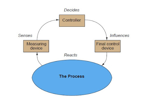
Consider following block diagram to understand some of the fundamental terms used in industrial instrumentation:
Instrumentation Basics
Process: The physical system we are attempting to control or measure. Examples: steam boiler, oil refinery unit, power generation unit.
Process Variable, or PV: The specific quantity we are measuring in a process. Examples: pressure,level, temperature, flow, electrical conductivity, pH, position, speed, vibration etc.
Setpoint, or SP: The value at which we desire the process variable to be maintained at. In other words, the “target” value for the process variable.
Primary Sensing Element, or PSE: A device directly sensing the process variable and translating that sensed quantity into an analog representation (electrical voltage, current, resistance; mechanicalforce, motion, etc.). Examples: thermocouple, thermistor, bourdon tube, microphone, potentiometer,
electrochemical cell, accelerometer etc.
Transducer: A device converting one standardized instrumentation signal into another standardized instrumentation signal, and/or performing some sort of processing on that signal. Often referred to as a converter and sometimes as a “relay.” Examples: I/P converter (converts 4-20 mA electric signal into 3-15 PSI pneumatic signal), P/I converter (converts 3-15 PSI pneumatic signal into 4-20 mA electric signal).
Note: in general science parlance, a “transducer” is any device converting one form of energyinto another, such as a microphone or a thermocouple. In industrial instrumentation, however, we generally use “primary sensing element” to describe this concept and reserve the word “transducer”
to specifically refer to a conversion device for standardized instrumentation signals.
Transmitter: A device translating the signal produced by a primary sensing element (PSE) into a standardized instrumentation signal such as 3-15 PSI air pressure, 4-20 mA DC electric current, Fieldbus digital signal packet, etc., which may then be conveyed to an indicating device, a controlling
device, or both.
Lower- and Upper-range values (LRV and URV): the values of process measurement deemed to be 0% and 100% of a transmitter’s calibrated range. For example, if a temperature transmitter is calibrated to measure a range of temperature starting at 300 degrees Celsius and ending at 500 degrees Celsius, its LRV would be 300 oC and its URV would be 500 oC.
Zero and Span: alternative descriptions to LRV and URV for the 0% and 100% points of an instrument’s calibrated range. “Zero” refers to the beginning-point of an instrument’s range (equivalent to LRV), while “span” refers to the width of its range (URV − LRV).
For example, if a temperature transmitter is calibrated to measure a range of temperature starting at 300 degrees Celsius and ending at 500 degrees Celsius, its zero would be 300 oC and its span would be 200 oC.
Controller: A device receiving a process variable (PV) signal from a primary sensing element (PSE) or transmitter, comparing that signal to the desired value (called the setpoint) for that process variable, and calculating an appropriate output signal value to be sent to a final control element (FCE) such as an electric motor or control valve.
Automatic mode: When the controller generates an output signal based on the relationship of process variable (PV) to the setpoint (SP).
Manual mode: When the controller’s decision-making ability is bypassed to let a human operator directly determine the output signal sent to the final control element.
Final Control Element, or FCE: A device receiving the signal output by a controller to directly influence the process.
Examples: variable-speed electric motor, control valve, electric heater.
Manipulated Variable, or MV: The quantity in a process we adjust or otherwise manipulate in order to influence the process variable (PV). Also used to describe the output signal generated by a controller; i.e. the signal commanding (“manipulating”) the final control element to influence the process.
 … in case of a thermocouple ‘heat’ energy to ‘electrical’ energy.