The Magnetic Level Gauge is the instrument to read a level indication in whatever plant or operating conditions giving free maintenance, preventive security against leakage, environmental safety, sure and trouble free application with chemically aggressive, pollutant, harmful or poisonous, inflammable or explosive, optically similar fluid interface.
Our very wide range of Magnetic Level Gauges allows to have the proper instrument for any kind of plant or specific purpose. Our world patented system includes a float able to float both in high density fluid or in low density fluid up to 0.4 specific gravity. But more! You can have low specific gravity and high temperature and pressure together (i.e. water/steam of H.P. vessels). Well! We manufacture a float able to float and to resist with external pressure of 210 bar at 370 ºC!
And more! Do you need Remote Direct Reading? We have it, as a completion of Magnetic or Glass level Gauge. Are you looking for a Transmitted Remote Signal? We can supply a sensing element able to transduce the signal to LED, Analogical or Recording Instruments that you can have in Control Room.
DESIGN
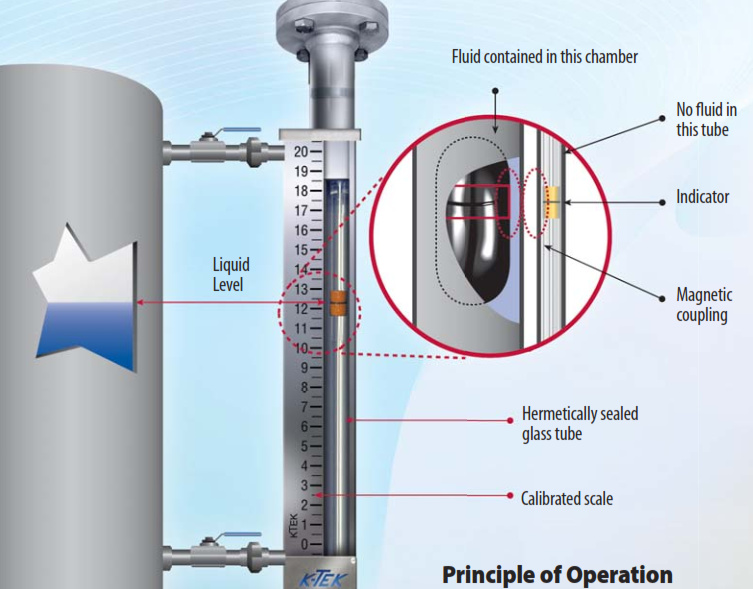
In a vertical chamber (tube of suitable diameter connected by stub ends to the vessel) there is a float containing a permanent magnet -fixed by means of special patented device that permit to the magnet a 360º rotation- placed exactly on liquid level line.
Magnetic action of permanent magnet in the float generates rotation of a set of small permanent magnets enclosed in small cylinders -contained in indicating scale- which cylinders, having different colours in the North and South pole, can rotate on their horizontal axis.
So the scale appears of one colour (i.e. white) over chamber area taken by gas and of another colour (i.e. red) over chamber area taken up by liquid phase.
The chambers of the Magnetic Level Gauge are dimensioned according to ASME B31.1 and B31.3.
The chamber is connected to vessel with flanged, threaded or welded ends. Usually, between the instrument and its connecting ends valves are fitted to consent shut-off piping and to disassemble the level gauge without empting the vessel or shutting off the plant. Drain valves can also be fitted on the top and bottom of level gauge.
MAGNETIC LEVEL GAUGE OPERATING PRINCIPLE
Operation of Magnetic Level Gauge is based on some elementary physical principles:
The principle whereby liquid in communicating vessels is always at same level;
Archimede’s principle according to which a body immersed in a liquid receives a buoyancy equal to the weight of displaced liquid;
The principle of attraction between North and South poles of two permanent magnets and that of repulsion between like poles.
This principle has two applications in the magnetic level gauge:
first between the magnet in the chamber float and every single magnet of the indicating scale:
second between the magnets of the indicating scale.
The cylindrical magnet “A” in the float is able to turn horizontally on the axis “B” like a compass needle, so that magnetic force is always free to best orientate itself towards the magnetic scale, in which small cylinders “C”, rotating vertically on their axis “D”, contain smaller cylindrical magnets fitted in orthogonal position to rotation axis.
Cylinders No. 1 & 2 are in stable position, as cylinders 4 & 5, because the magnetic chain between their magnets is well oriented “N-S-N-S”; cylinder No. 3 is in not stable position because North Pole “N” of the bigger magnet “A” inside the float attracts the South Pole “S” of the smaller magnet inside the cylinder. The same cylinder tries to rotate clockwise because its “N” pole would reach the “S” pole of cylinder 2. Imagine now that fluid, growing in the level gauge, pushes up the float.
The float magnet, going upside, will approach the cylinder 4, attracting its “S” pole, and so, after clockwise rotation, it will be in the same position as now the cylinder 3. Same cylinder 3 will be in that case free to complete rotation clockwise, and its position will became stable as cylinder 1 & 2. And so and so with growing of the liquid level. The same, with inverse rotation of small cylinders, happen when the float goes down.