The PLC representation of NO contact is given in Figure. This contact scans for the signal state ON (1) at the specified bit address. Power flows through NO contact if the scanned bit Bit address Output address Rung + 0 V Program logic Output coil Figure 1.1 Ladder diagram address has a signal state ON (1). This contact is used for scanning the signal state of input devices or output devices or other internal program elements.
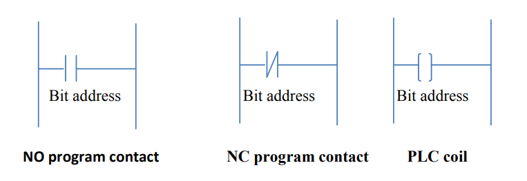
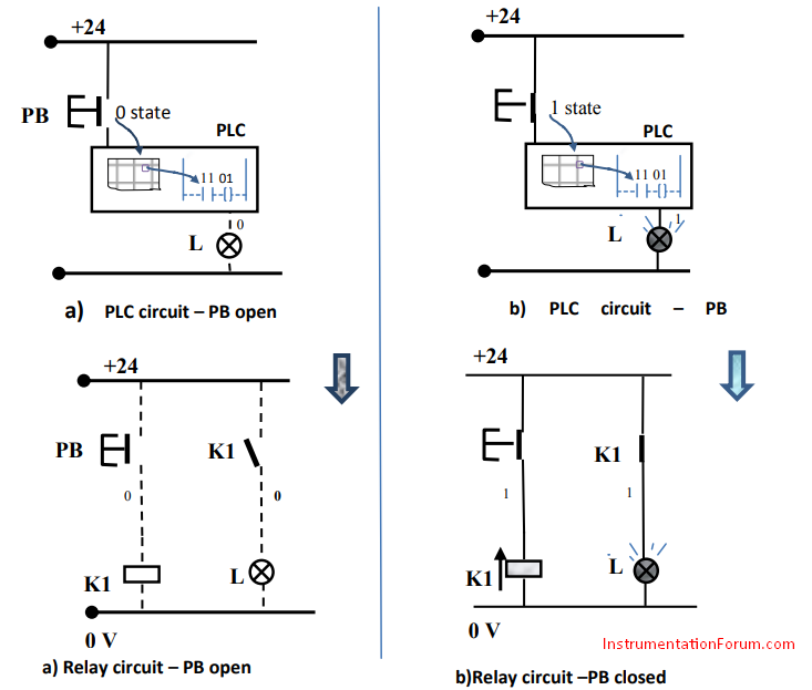
Figure 1.2 PLC circuit with NO contact position using NO push button