Since we frequently meet with concepts “normally open” and “normally closed” in industrial environment, it’s important to know them.
Both terms apply to words such as contacts, input, output, etc. (all combinations have the same meaning whether we are talking about input, output, contact or something else).
Principle is quite simple, normally open switch won’t conduct electricity until it is pressed down, and normally closed switch will conduct electricity until it is pressed.
Good examples for both situations are the doorbell and a house alarm. If a normally closed switch is selected, bell will work continually until someone pushes the switch.
By pushing a switch, contacts are opened and the flow of electricity towards the bell is interrupted. Of course, system so designed would not in any case suit the owner of the house.
A better choice would certainly be a normally open switch. This way bell wouldn’t work until someone pushed the switch button and thus informed of his or her presence at the entrance.
Home alarm system is an example of an application of a normally closed switch. Let’s suppose that alarm system is intended for surveillance of the front door to the house.
One of the ways to “wire” the house would be to install a normally open switch from each door to the alarm itself (precisely as with a bell switch). Then, if the door was opened, this would close the switch, and an alarm would be activated.
This system could work, but there would be some problems with this, too. Let’s suppose that switch is not working, that a wire is somehow disconnected, or a switch is broken, etc. (there are many ways in which this system could become dysfunctional). The real trouble is that a homeowner would not know that a system was out of order.
A burglar could open the door, a switch would not work, and the alarm would not be activated. Obviously, this isn’t a good way to set up this system. System should be set up in such a way so the alarm is activated by a burglar, but also by its own dysfunction, or if any of the components stopped working. (A homeowner would certainly want to know if a system was dysfunctional).
Having these things in mind, it is far better to use a switch with normally closed contacts which will detect an unauthorized entrance (opened door interrupts the flow of electricity, and this signal is used to activate a sound signal), or a failure on the system such as a disconnected wire.
These considerations are even more important in industrial environment where a failure could cause injury at work.
One such example where outputs with normally closed contacts are used is a safety wall with trimming machines. If the wall doors open, switch affects the output with normally closed contacts and interrupts a supply circuit.
This stops the machine and prevents an injury. Concepts normally open and normally closed can apply to sensors as well. Sensors are used to sense the presence of physical objects, measure some dimension or some amount.
For instance, one type of sensors can be used to detect presence of a box on an industry transfer belt. Other types can be used to measure physical dimensions such as heat, etc. Still, most sensors are of a switch type.
Their output is in status ON or OFF depending on what the sensor “feels”. Let’s take for instance a sensor made to feel metal when a metal object passes by the sensor.
For this purpose, a sensor with a normally open or a normally closed contact at the output could be used. If it were necessary to inform a PLC each time an object passed by the sensor, a sensor with a normally open output should be selected. Sensor output would set off only if a metal object were placed right before the sensor.
A sensor would turn off after the object has passed. PLC could then calculate how many times a normally open contact was set off at the sensor output, and would thus know how many metal objects passed by the sensor.
Concepts normally open and normally closed contact ought to be clarified and explained in detail in the example of a PLC controller input and output. The easiest way to explain them is in the example of a relay.
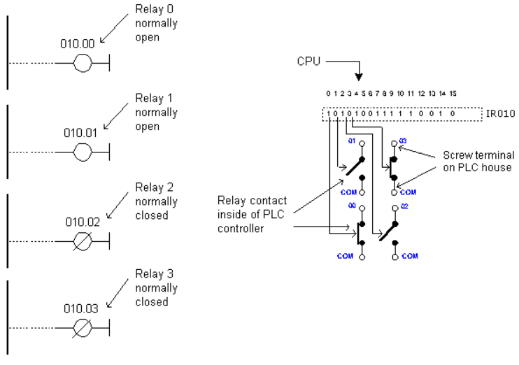
Normally open contacts would represent relay contacts that would perform a connection upon receipt of a signal. Unlike open contacts, with normally closed contacts signal will interrupt a contact, or turn a relay off. Previous picture shows what this looks like in practice.
First two relays are defined as normally open , and the other two as normally closed. All relays react to a signal! First relay (00) has a signal and closes its contacts. Second relay (01) does not have a signal and remains opened.
Third relay (02) has a signal and opens its contacts considering it is defined as a closed contact. Fourth relay (03) does not have a signal and remains closed because it is so defined.
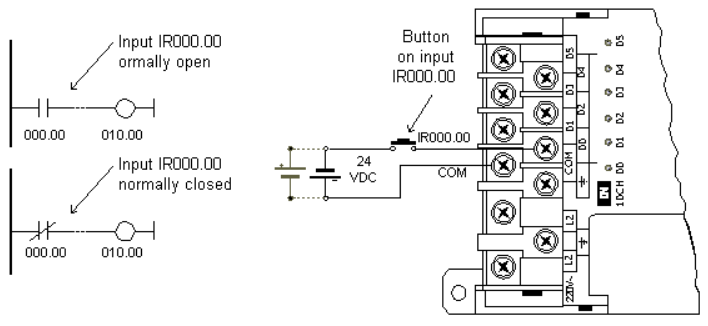
Concepts “normally open” and “normally closed” can also refer to inputs of a PLC controller. Let’s use a key as an example of an input to a PLC controller. Input where a key is connected can be defined as an input with open or closed contacts.
If it is defined as an input with normally open contact, pushing a key will set off an instruction found after the condition.
In this case it will be an activation of a relay 00. If input is defined as an input with normally closed contact, pushing the key will interrupt instruction found after the condition. In this case, this will cause deactivation of relay 00 (relay is active until the key is pressed).
You can see in picture below how keys are connected, and view the relay diagrams in both cases.
Normally open/closed conditions differ in a ladder diagram by a diagonal line across a symbol. What determines an execution condition for instruction is a bit status marked beneath each condition on instruction line.
Normally open condition is ON if its operand bit has ON status, or its status is OFF if that is the status of its operand bit. Normally closed condition is ON when its operand bit is OFF, or it has OFF status when the status of its operand bit is ON.
When programming with a ladder diagram, logical combination of ON and OFF conditions set before the instruction determines the eventual condition under which the instruction will be, or will not be executed. This condition, which can have only ON or OFF values is called instruction execution condition.
Operand assigned to any instruction in a relay diagram can be any bit from IR, SR, HR, AR, LR or TC sector. This means that conditions in a relay diagram can be determined by a status of I/O bits, or of flags, operational bits, timers/counters, etc.