Basic Steps In PLC Programming
The first step in developing a control program is the definition of the control task. The control task specifies what needs to be done and is defined by those who are involved in the operation of the machine or process. The second step in control program development is to determine a control strategy, the sequence of processing steps that must occur within a program to produce the desired output control.
This is also known as the development of an algorithm.
A set of guidelines should be followed during program organization and implementation in order to develop an organized system.
Approach guidelines apply to two major types of projects: new applications and modernizations of existing equipment .
Flow charting can be used to plan a program after a written description has been developed. A flowchart is a pictorial representation of the process that records, analyzes, and communicates information, as well as defines the sequence of the process.
Logic gates or contact symbology are used to implement the logic sequences in a control program. Inputs and outputs marked with an “ X ” on a logic gate diagram represent real I/O .
Three important documents that provide information about the arrangement of the PLC system are the I/O assignment table , the internal address assignment table , and the register address assignment table .
- The I/O assignment table documents the names, locations, and descriptions of the real inputs and outputs.
- The internal address assignment table records the locations and descriptions of internal outputs, registers, timers, counters, and MCRs.
- The register address assignment tablelists all of the available PLC registers.
Certain parts of the system should be left hardwired for safety reasons. Elements such as emergency stops and master start push buttons should be left hardwired so that the system can be disabled without PLC intervention.
Special cases of input device programming include the program translation of normally closed input devices, fenced MCR circuits, circuits that allow bidirectional power flow, instantaneous timer contacts, and complicated logic rungs.
- The programming of contacts as normally open or normally closed depends on how they are required to operate in the logic program . In most cases, if a normally closed input device is required to act as a normally closed input, its reference address is programmed as normally open.
- Master control relays turn ON and OFF power to certain logic rungs. In a PLC program, an END MCR instruction must be placed after the last rung an MCR will control.
- PLCs do not allow bidirectional power flow, so all PLC rungs must be programmed to operate only in a forward path.
- PLCs do not provide instantaneous contacts; therefore, an internal output must be used to trap a timer that requires these contacts.
- Complicated logic rungs should be isolated from the other rungs during programming.
Program coding is the process of translating a logic or relay diagram into PLC ladder program form.
The benefits of modernizing a relay control system include greater reliability , less energy consumption , less space utilization , and greater flexibility .
Example Of Simple Start/Stop Motor Circuit
Figure 1 shows the wiring diagram for a three-phase motor and its corresponding three-wire control circuit, where the auxiliary contacts of the starter seal the start push button. To convert this circuit into a PLC program , first determine which control devices will be part of the PLC I/O system ; these are the circled items in Figure 2 . In this circuit, the start and stop push buttons ( inputs ) and the starter coil ( output ) will be part of the PLC system.
The starter coil’s auxiliary contacts will not be part of the system because an internal will be used to seal the coil, resulting in less wiring and fewer connections.
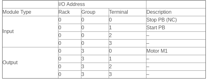
Table 1 shows the I/O address assignment , which uses the same addressing scheme as the circuit diagram (i.e., inputs: addresses 000 and 001 , output: address 030 ).
To program the PLC, the devices must be programmed in the same logic sequence as they are in the hardwired circuit ( see Figure 3 ). Therefore, the stop push button will be programmed as an examine-ON instruction ( a normally open PLC contact ) in series with the start push button, which is also programmed as an examine-ON instruction.
This circuit will drive output 030, which controls the starter.
If the start push button is pressed, output 030 will turn ON , sealing the start push button and turning the motor ON through the starter. If the stop push button is pressed, the motor will turn OFF .
Note that the stop push button is wired as normally closed to the input module. Also, the starter coil’s overloads are wired in series with the coil.
Resource: Introduction to PLC Programming and Implementation—from relay logic to PLC logic