Process Safety Limits
Many aspects of process safety management require knowledge of safe limit values for process variables.
For example, a hazard and operability study team needs to know the quantified meaning for terms such as “high temperature,” an inspector needs to know the corrosion allowance for vessels and pipes, an operator needs to know the maximum and minimum levels in tanks, and a management of change review team needs quantified information about the parameters that are being changed. If the value of a variable moves outside its safe range then, by definition, a hazardous situation has been created.
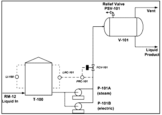
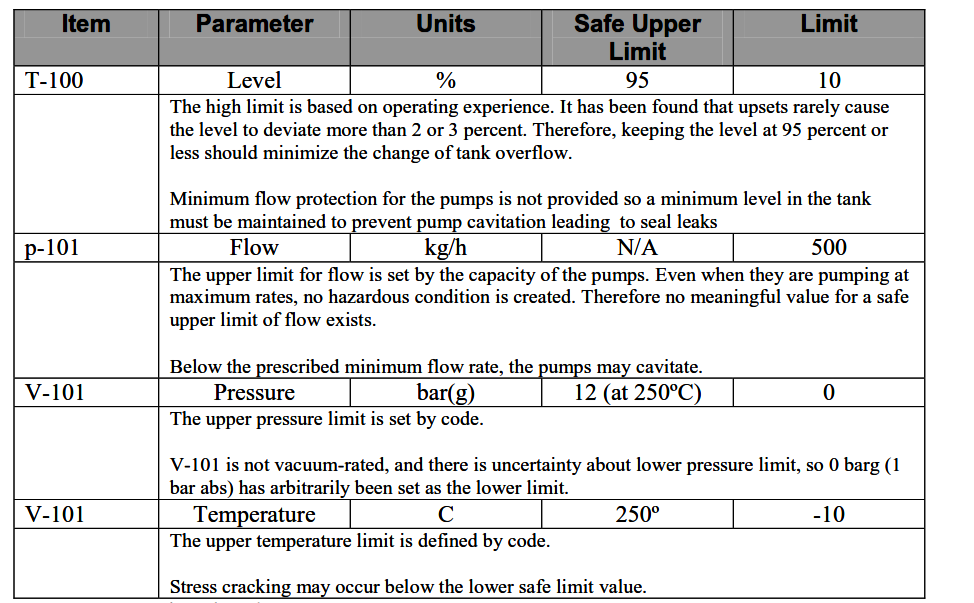
Table provides some examples for safe limit values for the equipment items in above figure. Table also provides some discussion to do with each value, showing where it came from, and what the impact of exceeding that value would be.
Above Figure provides another illustration of the safe limit concept (the values shown in figure could be for any process parameter such as pressure, temperature, level or flow).
Figure shows three ranges for the process parameter in question. The first is the normal operating range; it lies between 218 and 245 (in the appropriate units of measurement).
Normal operations are carried out within this envelope. If the value is allowed to go outside the range it is likely that production or quality problems will crop up. If an operating value goes outside the operating range, but stays within safe limits, then the facility is in “trouble”.
There is no perceived safety or environmental problem during this phase of the operation, but the facility may be losing money.
Examples of trouble in this context include
- excessive steam consumption
- product quality problems
- unusually high consumption of spare parts
- production flow limitation problems
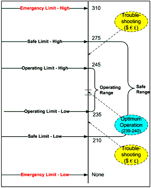
Figure 59. Example of safe limit range
The second range lies between the safe upper limit and the safe lower limit (210 - 275 in figure 59). These parameters are sometimes referred to as “Not to Exceed” limits. If the value of the parameter goes outside this range then the process is, by definition, unsafe, and action must be taken.
The option of doing nothing is not an option. It is likely that, once these safe limits are breached, safety devices, particularly instrumentation systems, will be activated. Operations personnel should understand the consequence of exceeding the limits; they should also be provided with procedures and training as to what actions to take to bring the variable back into the safe range. If the operations team wishes to operate outside the safe range, say to increase production rates, they can only do so after implementing the management of change process.
The third range shown in figure 59 defines emergency conditions. If a variable value goes outside the emergency limit range, urgent action is required. It is probable that an excursion outside the safe limits will lead to activation of emergency instrumentation and mechanical safety devices, such as pressure relief valves. Some safe limits may have no meaningful value.
For example, if a pressure vessel is designed for full vacuum operation, then that vessel has no safe lower limit for pressure. In table 5, no value for a safe upper limit for high flow is provided because the system is safe even when the pumps are running flat-out with all control valves wide open.
MAXIMUM ALLOWABLE WORKING PRESSURE (MAWP)
One particularly important safe limit value to understand is that of maximum allowable working pressure (MAWP) for pressure vessels. Since the concept of MAWP is so important, and since it is not always well understood, the following guidance, based on ASME terminology using V-101 in figure 58 as an example is provided.
As the process design is being developed, the process engineers require that V-101 be designed for a maximum pressure of 95.0 psig. This is the design pressure or pressure rating of the vessel (it is measured at the top of the vessel). The process engineer’s target values are transmitted to the vessel engineer. He or she designs the vessel using standard sizes for wall thickness and flange size, thus generating the MAWP, which is the maximum pressure at which the vessel can be operated.
Generally MAWP is higher than the design pressure because wall thicknesses are in discrete sizes, and the designer will always choose the standard value greater than that called for. In the example, since it is unlikely that he/she can design for exactly 95.0 psig, the designer selects the next highest level, which turns out to give a MAWP of 120.0 psig.
Once the vessel is in operation, the vessel can be operated at up to 120 psig without exceeding its safe limits. MAWP is the pressure that will be used for setting relief and interlock values. The test pressure for the vessel is 1.5 times design pressure. Anytime the vessel is opened, it will be tested to that pressure before the process is restarted.
If the pressure goes above test pressure, the vessel walls are close to their yield point. Up to twice the MAWP value the vessel or associated piping may be slightly distorted, but any leaks are most likely to occur at gaskets. At 2 to 4 times MAWP, there will probably be distortion of the vessel, and it can be assumed that gaskets will blow out.
The vessel’s burst pressure will typically be in the range of 3.5 to 4 times MAWP. Therefore, for this example, the burst pressure would be between 400 and 500 psig. (It is difficult to predict this value accurately because so few vessels actually fail, so there is not much field data.)
Because temperature affects the strength of a vessel (higher temperatures make the metal yield more easily), the MAWP has an associated temperature. The effect of high temperature on equipment strength can be very deleterious.
For example, the MAWP for a certain vessel may be 150 psig at a temperature of 600ºF. At 1000ºF, the same piece of equipment will fail at just 20 psig. On the other hand, at 100ºF, it may be able to handle nearly 300 psig. Hence, when temperatures are changing, the nominal pressure rating can be very misleading. (In this context, metal temperature refers to the average metal temperature through its entire depth.)
Although the MAWP should never be exceeded during normal operation, it may be acceptable for the operating pressure to go above the MAWP for brief periods of time, say during an emergency situation. However, following such an excursion, the vessel should be checked by a qualified vessel expert before being put back into service. If equipment and piping are designed by rigorous analytical methods, such as finite element analysis, it is possible to operate with a lower safety margin than is required by the use of MAWP.