For managing and control of the electrical systems there once were used electromechanical relays. In time as tehnology advanced came and PLC devices.
Also there is the finance aspect since now PLC are cheaper then relays.
PLC Components
Every PLC is consists from a couple components. Each manufacturer gives his combination but we can disassemble an PLC on his key elements:
- Power source
- CPU
- Input modul
- Output modul
There are tree sizes of a PLCs: Mini, medium or rack.
Each of above mentioned parts of PLC must be supplied with power (the common beginners mistake is that they connect only one modul of a PLC to power source and then only that modul works).
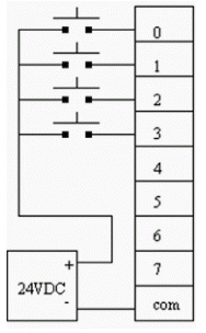
We can supply moduls with AC or DC current variously of our needs. In most of cases on module we have a COM conector which is wired to a “-“ end if DC or a “0” end if AC and each connector of that modul must be supplied with a “+” end of power source (if we are using AC the correct term is “hot” wire).
An example of wiring power supply and module is showed in Figure 1
Input modules are important because they convert monitored value into a electrical signal (namely into bits). Output moduls turn electrical bits into signals that acts on actuator.
Programming of a PLC
Programing is done in a ladder programming environment ,this way is adopted from anology with relays because with this there were less time needed to retrain technicians and engineers who has already worked with relays.
After understanding the problem and before beginning programming we need to “collect” all Input/Output(I/O) signals. Beetwen I/O moduls is CPU.
Before we begin programming we need to define some basic terms:
Bitbox – as the name says it is a box containing a bit (it can hold only two bits:0 or 1) from whose value depends behavior of instruction (it is very important to remember that this box is virtual)
Instruction – action inside program that needs to check hers bitbox in order to execute .
Enviroment in which is programming being done varies from manufacturer of an PLC device but symbols are the same so we can work in different programs without big differences. On next pictures we can see RSLogix program.
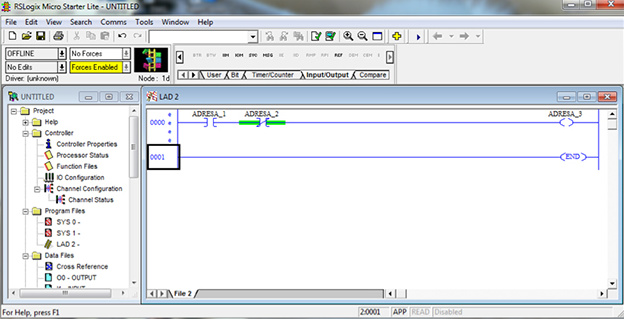
From Figure 2 we can see why it is called ladder programming (we have two vertical lines between which is horizontal lines with instructions-rangs)
We will explain some of symbols that can be seen while programming :
![]()
This is XIC instruction . The most important thing is to understand what this instruction does and how she does it. There are numerous interpretation of this instruction but in mine opinion the easiest for beginner is : “ Go look for 1 ”.
Basically program tells instruction “ go look for 1 ”,someone would ask where to look? Above instruction there is address of bitbox that need to be checked. If in bitbox, with address in this example “ADRESA_1”,contains 0 then instruction is FALSE,while it gets 1 and then instruction is TRUE.
This is XIO instruction . This instruction can be interpreted as “Go look for 0”,which it seeks inside bitbox with a address “ADRESA_2” .
![]()
OTE instruction represent excecutive command . It can be interpreted as “Go write 1” in bitbox with “ADRESA_3”. In order that this instruction gets TRUE value and therefore “write 1”in bitbox it need to have continues line of TRUE from left to the right side in a rang. Respectivelly if we have FALSE coming the instruction interprets this as “Go write 0”.
Let us take a look at an example in Figure 2. In order to excecutive command “ writes 1 ” we need to have next values inside bitboxes:
| ADRESA_1 | 1 |
|---|---|
| ADRESA_2 | 0 |
Explanation:
Program starts with XIC instruction and “ looks for 1 ” if there is inside bitbox with adress “ADRESA_1” value 1 then this instruction is TRUE,next we have XIO instruction that “ looks for 0 ” on address “ADRESA_2” and if bitbox has value 0 then this instruction is also TRUE. Since we have continuos TRUE from left to right executable instruction “ goes and writes 1 ” inside bitbox “ADRESA_3”.
After that we can see that program ends and process start again.

Instruction “LATCH” that is excecutable, has characteristic that if TRUE comes to it it “Write 1” same as OTE instruction but if we have FALSE coming then this instruction has command “do nothing”.
![]()
Opposite of instruction latch we have instruction “ UNLATCH ” that if has TRUE coming to it it interprets as “ Go write 0 ” but if it has FALSE coming to her she inreprets as “ do nothing ”.
Timers
One more instruction we have are timers. There are four basic types of timers which are illustrated in the following table:
| On-delay | Off-delay | |
|---|---|---|
| With memory | RTO | RTF |
| Without memory | TON | TOF |
Timer with On-delay without memory (RTO) works in the following way: When TRUE comes timer starts counting time inside accumulator (which has 0 value in the example below) and counts time until preset(which is set to value 4000 in example,that is 4s) after what it excecutes instruction DN.
Advantage of an PLC devices over relays is that they can be used for a different problems with the same hardware, while relays must be again rewired to do some other function.