Creating SIF validation procedures
Implementing safety system validation as part of the safety lifecycle is defined by IEC 61511 and ANSI/ISA-S84.01. Here’s how it’s done.
 A process safety system comprises many individual safety instrumented functions (SIFs) designed to move a plant or process unit to a safe state when something goes wrong. These functions should happen automatically—following a specific plan—when an undesired condition arises.
For example, a steam-heated reactor will be equipped with a pressure sensor able to determine if it has moved beyond its safe operating range. The SIF will have a trip point where the controller (the SIF’s logic solver), will do something specific to remediate the situation. In this case, it opens a relief valve to keep pressure in the reactor from going any higher and might cut off steam flow. This action, or perhaps actions, happen automatically when the pressure reaches the prescribed setpoint following the plan designed by safety engineers to avoid any possibility of the reactor or its associated piping exploding (see “Designing a SIF” at the end of the story).
While a process is being designed, particularly one where products are flammable or toxic, safety specialists study it carefully to determine all the areas where things could go wrong. For example, what if this valve sticks? What if the reactor gets too hot? Could this tank overflow? Then, safety specialists imagine what kinds of havoc or damage these situations could cause if realized, and the likelihood of a problem actually developing.
If they believe the consequences of the specific problem occurring are beyond what the company is willing to risk, safety specialists design a remedy and create a SIF to carry it out. In a complex unit, there can be hundreds of individual SIFs. The hazards they cover may overlap, creating multiple layers of protection. Therefore, if one fails or proves to be inadequate, another remains to avoid a more drastic escalation.
![]()
Each SIF is assigned a safety integrity level (SIL), which in basic terms is its importance in the larger risk-reduction picture. Every SIF is important, but some are more so. Those with high SIL ratings are especially critical, and the remedy has to provide a major reduction in the probability that the event will happen. Those with low SIL ratings may have smaller consequences, or there may be other mechanisms that are capable of solving the problem, so the degree of risk reduction would be less. (See editor’s note.)
Safety specialists design the SIFs and then oversee their installation and maintenance for as long as the plant is in operation. This safety lifecycle (SLC) concept ties together all the steps in implementing a complete safety system, or one SIF. It follows three main phases: analysis, realization, and maintenance. It begins with the initial analysis of the process and hazard identification, and then moves to developing a mechanism to protect against the event, including installation and ongoing support.
The role of the safety specialist in this context cannot be overemphasized. The suggestions for designing and implementing safety functions offered here should be left to qualified safety specialists. While it is important to understand how these things work, implementing them yourself if you don’t have the proper training is not a good idea and could potentially be disastrous. To apply a common expression, don’t try this at home.
Will it work?
After a SIF is installed, it must be validated to verify its operation. Validation must follow specific procedures to ensure it is trustworthy, with all steps documented. The validation process puts the SIF under a microscope, dissects it, and looks for all the ways in which it could fail. Each of those possibilities must be examined and tested, one by one, element by element. Proof tests are conducted at prescribed intervals to detect undetected dangerous failures that could prevent the SIF from working in the future. Sensors, logic solvers, and final elements can be tested separately at different intervals, or the entire SIF can be proof tested at once. Eventually, the specific SIF or the complete safety system may be decommissioned with a given process unit or entire plant, bringing an end to its lifecycle.
The term “validation” is critical. There are many kinds of tests and checks performed when a unit is being constructed or upgraded. Terms such as software verification, loop checks, proof tests, factory acceptance test, and others can be used for other things. But a safety system validation must follow a specific approach spelled out in an applicable standard and must be documented in a specific way. Other tests also may be just as specific, but typically they may have different objectives.
A step in the safety lifecycle
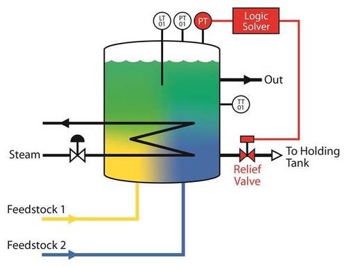
Validation of a SIF is only one step in the larger SLC, but it is critical. Figure 1 shows a hypothetical example of a typical SIF applied to a continuous process. In this example, two liquid feedstocks are pumped into a reactor, and then heated and agitated so they form a new compound that flows out of the reactor near the top. Temperature, pressure, and level are measured with TT01, PT01, and LT01 respectively.
The hazard analysis warns of a possible overpressure incident if the output flow is obstructed, thus the designers specify a SIF capable of creating a second outlet to allow some of the contents to pass to a holding tank. This may not be the only SIF connected with the reactor. There could be another SIF designed to shut off the steam to the heater if the temperature becomes too high, or feedstock inputs might be cut off if the level in the reactor gets too high.
Under normal operating conditions, the basic process control system (BPCS) keeps these parameters on an even keel. For this example, it probably would do a good job more than 99.99% of the time. Unfortunately, in the real world, things can and do go wrong. The steam control valve might stick or the pump extracting the product from the reactor may fail. In those cases, the BPCS can’t always address the situation, and the SIF must step in and do its job.
Many potential variables
While reviewing the hypothetical process, the choices the SIF designer must make include:
- The type of pressure instrument to use
- Pressure instrument location
- Valve response time after trip
- Pipe and valve sizes sufficient for pressure relief
- Trip pressure setting
- Self-resetting versus non-self-resetting loop
- The information that should be sent to the BPCS.
When these parameters are set, the equipment can be installed and is ready for validation. This is the moment of truth when everything must work, despite every attempt by those doing the testing to make it fail. Given its critical nature, validation must be a careful and well-thought-out process in compliance with relevant standards, and it must be fully documented. Performing the series of tests required might be a complex process and involve a variety of other plant personnel, as exemplified by these typical steps:
- Identify all pieces of equipment or systems connected to the SIF under test. Obviously, the safety devices themselves are included, but there may be others involved tangentially. The SIF equipment must function independently, but performing the test may require bypassing another system, disabling an alarm, or changing an element of the process.
- Involve all of the departments and people who will be participating or are affected by the process and get their input. The primary areas to include are operations, maintenance, process control, and process safety. But never underestimate the number of individuals who might feel they should be involved. Ask for input and assistance as needed because the test will invariably affect other areas, especially operations and maintenance.
- Create the testing process and put it in writing. Because the test must be documented, it must follow a specific procedure.IEC 61511 and ISA 84 specify the general steps the test must include, so make sure it follows those recommendations. Each step should indicate the desired outcome, following the potential failure modes identified by the system designers. The SIL rating may come into play because a SIF with a high SIL rating may need more extensive testing than one with a low SIL. The procedure also must be practical within the plant context, so it must be selected carefully. In most companies, a basic procedural template can be set up and adjusted for each situation, so it won’t be necessary to start from scratch for every SIF.
- Determine and document advance preparations of the equipment necessary to perform the test, along with any unusual equipment to have on hand, such as a stopwatch. If a pipe must be drained or the liquid in a tank moved to a specific level, these requirements must be noted. If step 2 was executed correctly, this will be easier.
- Communicate the testing instructions. Be specific as to who needs to be where, what they need to be doing, and when their activities must take place. Again, cooperation and success in this step depends on step 2. Some tests will address the SIF as a unit, while others will examine individual components.
- Specify in detail which variables must be recorded during the tests. What value did the pressure instrument actually display? How long did it take for the actuator to respond to the signal? Did it respond as quickly as it needs to in actual service? This where the stopwatch might come in handy. If the response time is too fast for a stopwatch, some other mechanism might need to be used, such as an event or alarm log on a software program connected to the process.
- Communicate instructions for return-to-service after the test is complete.
- This test may be performed only once, but because there is potential for the SIF to be updated or otherwise modified, the procedure should include a revision history.
Learn more simulations dangers and advice on how to design an SIF.