first examples are general ladder logic examples. These examples can be used in almost every ladder logic PLC program.
If you need a simple function implemented in your ladder logic, you can use the general examples. General ladder logic examples can almost always be copied into your own ladder diagrams. The only thing you need to edit, is the names and the symbols for the bit logic instructions.
At last you will find real-world PLC ladder logic examples. This is a collection of PLC programs from the real-world, where simulations, videos or photos are a part of the example. Real-world PLC examples from a factory or a traffic light can be very useful, when you are searching for inspiration. These examples can rarely be copied to fit your own project, but you can use chunks and ideas from the real-world examples.
Before exploring i want to say how many types of ladder logic programs
-
Simple Ladder Logic Program Examples
- Simple Start/Stop Ladder Logic Relay
- Single Push Button On/Off Ladder Logic
-
Ladder Logic Examples with Timers
- PLC Program Example with On Delay Timer
- PLC Program Example with Off Delay Timer
- PLC Program Example with Retentive Timer
-
Ladder Diagram for Motor Control
- Star Delta PLC Ladder Diagram
- Ladder Diagram for DOL Motor Starter
-
PLC Program Examples From The Real World
- Traffic Light Ladder Logic Diagram
- Ladder Diagram for Bottle Filling Plant
- PLC Ladder Diagram for Elevator Control
Lets start with basic start and off
Simple Start/Stop Ladder Logic Relay
This is how the ladder diagram looks for a simple start/stop function. The function can be used to start and stop anything like a motor start/stop.
In this ladder logic example, there are two inputs.
- “Start button” or PLC input I0.0.
- “Stop button” or PLC input I0.1.
The start button will activate the relay, or ladder logic relay M10.0. When the start button is released, the relay will still be activated, because of the latch in ladder rung 2. This latching will be broken when the stop button is activated.
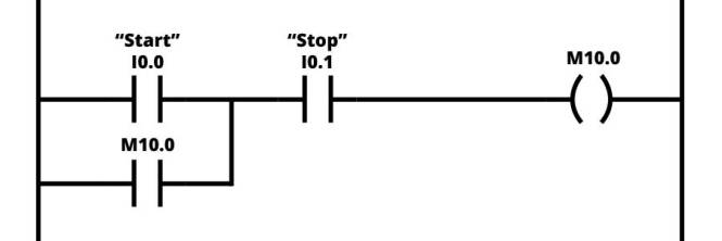
You might wonder why the stop button in this example is normally open. And the reason for that, is that y ou should use normally closed as stop button, to avoid dangerous situations under failure.*
Single Push Button On/Off Ladder Logic
This function is also called push on push off logic sometimes even flip-flop or toggle function . It is the same function as the on/off button on your computer or mobile phone. When you push the button the first time, the output will be activated. Now, when you push the button for the second time, the output will deactivate and turn off. The single push button has two functions: on and off.
Push on push off logic can be done in several ways. It can be done by using ladder logic and boolean logic instructions or it can be done with a counter. It can even be done with PLC rising edge and falling edge triggers or with shift registers.
Here is the example using boolean logic instructions only (complicated version):
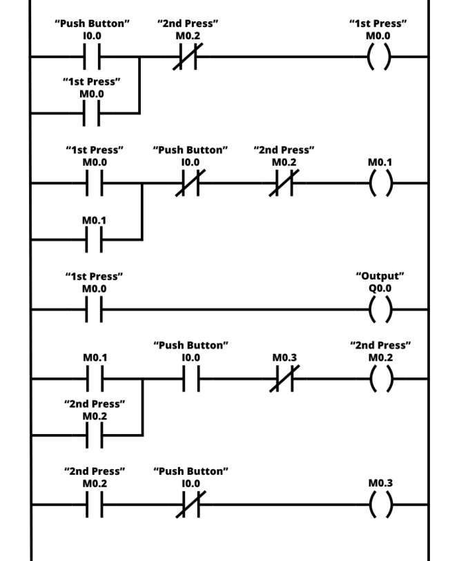
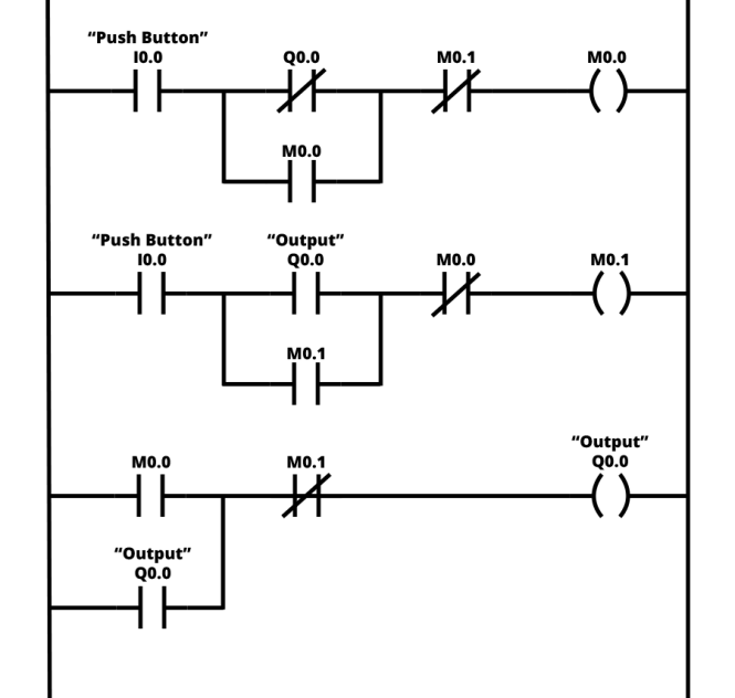
But… there is a faster way to make the same toggle function with a single push button:
The example is from Mayur Haldankar’s blog about PLC programming and DSP (digital signal processing). He even has examples of DSP programs written in C++.
In his example, he uses 3 (4) rungs only to make the toggle function of a push button (simple version):
Ladder Logic Examples with Timers
PLC program examples with timers in ladder logic. Generally speaking, you have three types of timers available in ladder logic. The on-delay timer, the off-delay timer and the retentive timer.
PLC Program Example with On Delay Timer
The first type of timer in ladder logic is the on delay timer. Its name comes from the fact, that the on delay timer delays its output from the on signal.
As soon as the on delay timer gets a signal at the input , the timer starts to count down. When the preset time is up, the output of the on delay timer will turn on. If the input is turned off before the count down finish, the time will reset.
On delay timers in ladder logic can look different depending on the PLC programming software. But common for all of them are the following:
- Input
- Enable Output (EN)
- Done Output (DN)
- Preset Time Value
The enable output (EN) is the first output and it is on when the timer is energized. So, as long as the input is true or on, the enable output will be true.
Second output is the done output (DN). This output in an on delay timer is only on, when the timer has counted down the preset time.
Source: Electrical Basic School Blog