Thermowell is used in measuring the temperature of a moving fluid, where the stream exerts an appreciable force and the sensitive element cannot be placed directly into the medium whose temperature is to be measured.
A thermowell is a pressure-tight receptacle that is adapted to receive a temperature sensing element and is provided with a variety of process connections (flanges, external threads or a machined shoulder) for tight pressure attachment to a process fitting.
The purpose of this example problem is to determine whether or not a thermowell selected for temperature measurement is strong enough to withstand specific application conditions of temperature, pressure, velocity and vibration.
Proper design of a thermowell requires that the sensor mounted inside the thermowell attain thermal equilibrium with the process fluid. Thermal modeling of the sensor response is outside the scope of this Standard (refer to the latest version of PTC 19.3 for guidance).
Thermowell Design
Adhering to a few general design rules will optimize the sensor performance within the constraints of the mechanical strength requirements.
A high fluid-velocity rating for the thermowell requires a sufficiently high natural frequency for the thermowell and sufficiently low oscillatory stresses.
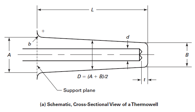
Higher natural frequencies result from decreasing the unsupported length, L, increasing the supportplane diameter, A, and decreasing the tip diameter, B. Lower oscillatory stresses result from decreasing length, L, and increasing diameter, A.
A higher static pressure rating requires increasing the value of tip diameter B. In contrast, good thermal performance favors increasing length, L, and decreasing diameters, A and B.
In addition, if the thermowell is to be evaluated in accordance to ASME PTC 19.3 TW, it is fit for service if it meets these four quantitative criteria:
(a) Frequency Limit. The resonance frequency of the thermowell shall be sufficiently high so that destructive oscillations are not excited by the fluid flow.
(b) Dynamic Stress Limit. The maximum primary dynamic stress shall not exceed the allowable fatigue stress limit.
(c.) Static Stress Limit. The maximum steady-state stress on the thermowell shall not exceed the allowable stress, as determined by the Von Mises criteria.
(d) Hydrostatic Pressure Limit. The external pressure shall not exceed the pressure ratings of the thermowell tip, shank, and flange.
In addition, the suitability of the thermowell material for the process environment shall be considered.
Download:
Thermowell Design.pdf (460.2 KB)