The real time examples for Phasor Groups of transformer are given here. These Phasor Groups can be better understand by the following examples. The Vector diagrams are given in the name plate details of the transformer.
Every Transformer Contains its own Vector Group as shown below figure.

Transformer Name Plate
Example-1:
As shown in the figure the Vector Group is Dyn11

Dyn11 Vector Group
The following information is obtained from the Vector diagram.
- The primary side is Delta denoted by D
- The secondary side is Star with Neutral Connection denoted by yn
- NUMBER (11) denotes phase displacement between HV and LV emfs expressed as clock hour number.
Here Dyn11 represents
A poly phase transformer with HV winding in Delta, LV winding in star with neutral and the LV line phasor 11 O’clock i.e. 30° ahead of the zero hour position of the HV line phasors.
As shown in the above figure the transformer is having 3 phases on HV Side (1U,1V,1W) and 3 Phases on LV Side (2U,2V,2W).
It means the LV Side U phase Vector 2U leads the HV Side U phase Vector 1U by 30°.
It is applicable to other phases also.
LV Side V phase Vector 2V leads the HV Side V phase Vector 1V by 30°.
LV Side W phase Vector 2W leads the HV Side W phase Vector 1W by 30°.
Example-2:
As shown in the figure the Vector Group is Dyn1

Dyn1 Vector Group
The following information is obtained from the Vector diagram.
- The primary side is Delta denoted by D
- The secondary side is Star with Neutral Connection denoted by yn
- NUMBER (1) denotes phase displacement between HV and LV emfs expressed as clock hour number.
Here Dyn1 represents
A poly phase transformer with HV winding in Delta, LV winding in star with neural and the LV line phasor 1 O’clock i.e. 30° behind of the zero hour position of the HV line phasors.
As shown in the above figure the transformer is having 3 phases on HV Side (1U,1V,1W) and 3 Phases on LV Side (2U,2V,2W).
It means the LV Side U phase Vector 2U lags the HV Side U phase Vector 1U by 30°.
It is applicable to other phases also.
LV Side V phase Vector 2V lags the HV Side V phase Vector 1V by 30°.
LV Side W phase Vector 2W lags the HV Side W phase Vector 1W by 30°.
Example-3:
As shown in the figure the Vector Group is YNd11.
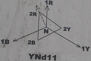
YNd11 Vector Group
The following information is obtained from the Vector diagram.
- The primary side is Star with Neutral Connection denoted by YN
- The secondary side is Delta Connection denoted by d
- NUMBER (11) denotes phase displacement between HV and LV emfs expressed as clock hour number.
Here YNd11 represents
A poly phase transformer with HV winding in Star with neutal, LV winding in delta and the LV line phasor 11 O’clock i.e. 30° ahead of the zero hour position of the HV line phasors.
As shown in the above figure the transformer is having 3 phases on HV Side (1R,1Y,1B) and 3 Phases on LV Side (2R,2Y,2B).
It means the LV Side R phase Vector 2R leads the HV Side R phase Vector 1R by 30°.
It is applicable to other phases also.
LV Side Y phase Vector 2Y leads the HV Side Y phase Vector 1Y by 30°.
LV Side B phase Vector 2B leads the HV Side B phase Vector 1B by 30°.