The opposition to the flow of current in an AC circuit
2 Likes
Resistance to electrical flow in an AC circuit. It is designated by the symbol Z and is expressed in ohms.
1 Like
Electrical impedance is the total opposition that a circuit presents to alternating current. Impedance is measured in ohms, and may include resistance, inductive reactance, and capacitive reactance.
However, the total impedance is not simply the algebraic sum of the resistance, inductive reactance, and capacitive reactance. Since the inductive reactance and capacitive reactance are 90º out of phase with the resistance and, therefore, their maximum values occur at different times, vector addition must be used to calculate impedance.
Source: NDT Resource Center, Impedance
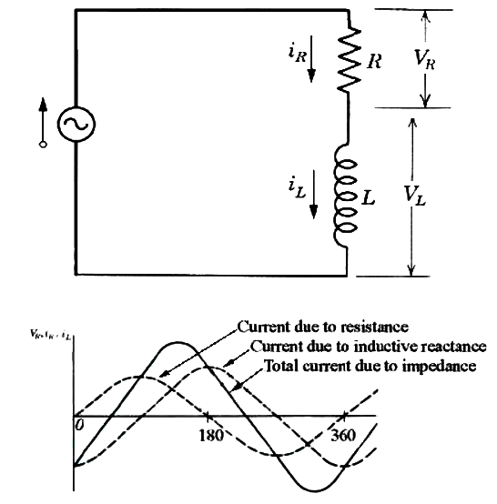
In figure, a circuit diagram is shown that represents an eddy current inspection system. The eddy current probe is a coil of wire that contains resistance and inductive reactance when driven by alternating current.
The capacitive reactance can be eliminated as most eddy current probes have little capacitive reactance. The solid line in the graph shows the circuit’s total current, which is affected by the total impedance of the circuit. The two dashed lines represent the portion of the current that is affected by the resistance and the inductive reactance components individually. It can be seen that the resistance and the inductive reactance lines are 90º out of phase,
so when combined to produce the impedance line, the phase shift is somewhere between zero and 90º. The phase shift is always relative to the resistance line since the resistance line is always in-phase with the voltage. If more resistance than inductive reactance is present in the circuit, the impedance line will move toward the resistance line and the phase shift will decrease.
If more inductive reactance is present in the circuit, the impedance line will shift toward the inductive reactance line and the phase shift will increase The relationship between impedance and its individual components can be represented using a vector as shown in below figure . The amplitude of the resistance component is shown by a vector along the x-axis and the amplitude of the inductive reactance is shown by a vector along the y-axis.
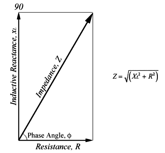
The amplitude of the impedance is shown by a vector that stretches from zero to a point that represents both the resistance value in the x-direction and the inductive reactance in the y-direction. Eddy current instruments with impedance plane displays present information in this format. The impedance in a circuit with resistance and inductive reactance can be calculated using the following equation. If capacitive reactance was present in the circuit, its value would be added to the inductance term before squaring.