There are two separate instructions required to make a Master Control program work.
Quite simply one instruction marks the beginning of the Master Control (MC), the other instruction marks the end of the Master Control (MCR).
Some points worth remembering about MC and MCR now follow;
Both MC and MCR are special output conditions, which use outputs, Y or internal flags, M. Hence they always appear last on a line of program. On the ladder diagram the MC and MCR symbols are the first instructions from the right hand side bus bar.
Master control constructions are not jumped by the program scan; even if they are not activated, i.e. all inputs and outputs are continually monitored and refreshed.
All MC instructions contain two pieces of information, the nesting level which is identified by a nest pointer and a control bit which activates the sub-program under that master control.
A master control construction can have up to eight control or nesting pointers. These pointers are represented by the N numbers in the MC and MCR instructions.
Master control constructions can be written, if required, by using only one control pointer. However each master control must still have a different control bit for the program to work correctly.
When a master control is reset by using the MCR if any further master control constructions are active below the reset nesting level, then those following master control constructions will also be reset.
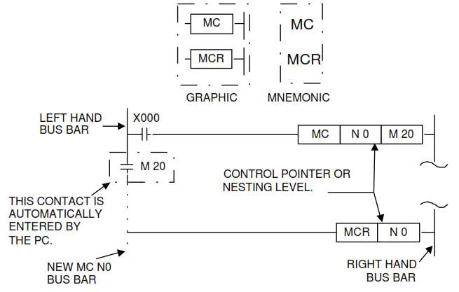
What do MC and MCR contacts look like?
In ladder format the MC and MCR instructions appear as shown in the following diagram. The diagram also shows the relative location where either an MC or an MCR can be found within a ladder rung.
Download
Master Control Instructions.PDF (66.5 KB)