Sinking and sourcing circuits are often a source of confusion for people newly introduced to the concept, especially people not familiar with the field of electronics.
PLC Sink and Source
Once the concept is understood new questions emerge such as: Which circuit is required for their application? How do they determine which circuit would work best?
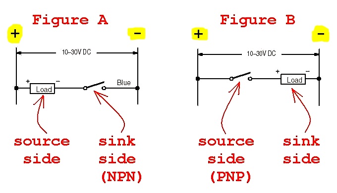
Suppose that you have a SOURCING-TYPE PLC input module (for example type 1746-IV16) … that module would play the part of the “LOAD” in Figure A above … the solid state sensor that you’d need to connect would be a SINKING-TYPE sensor – also known as an NPN-type sensor …
notice that the description above gives us ONE “sourcing-type” device and ONE “sinking-type” device to use in our circuit … the “sourcing device” goes on the PLUS/POSITIVE side … the “sinking device” goes on the MINUS/NEGATIVE side …
now then …
suppose that you have a SINKING-TYPE PLC input module (for example type 1746-IB16) … that module would play the part of the “LOAD” in Figure B above … the solid-state sensor that you’d need to connect would be a SOURCING-TYPE sensor - also known as a PNP-type sensor …
notice that (just like before) the description above gives us ONE “sourcing-type” device and ONE “sinking-type” device to use in our circuit … and (once again) the “sourcing device” goes on the PLUS/POSITIVE side … the “sinking device” goes on the MINUS/NEGATIVE side …
going one step further …
now instead of input modules suppose that we talk about the PLC output modules instead …
suppose that you have a SINKING-TYPE PLC output module (for example type 1746-OV16) … that module would play the part of the “SWITCH” in Figure A above … the “LOAD” that you’d need to connect would be a SOURCING-TYPE field device …
notice that (as before) the description above gives us ONE “sourcing-type” device and ONE “sinking-type” device to use in our circuit … and (once again) the “sourcing device” goes on the PLUS/POSITIVE side … the “sinking device” goes on the MINUS/NEGATIVE side …
now then …
suppose that you have a SOURCING-TYPE PLC output module (for example type 1746-OB16) … that module would play the part of the “SWITCH” in Figure B above … the “LOAD” that you’d need to connect would be a SINKING-TYPE field device …
notice (again) that the description above gives us ONE “sourcing-type” device and ONE “sinking-type” device to use in our circuit … the “sourcing device” goes (as always) on the PLUS/POSITIVE side … the “sinking device” goes on the MINUS/NEGATIVE side …
nailing down the “big picture” ideas:
your basic DC circuit needs ONE “SOURCING” type device - and ONE “SINKING” type device … the “SOURCING” device always goes on the PLUS/POSITIVE side … the “SINKING” device always goes on the MINUS/NEGATIVE side …
Survival tip: don’t think of the words “source” and “sink” of telling where the “juice” is actually coming from - and where it’s going to … instead just remember that the “source” thing goes with PLUS/POSITIVE -and that the “sink” thing goes with MINUS/NEGATIVE …
another thought that just occurred to me …
make sure that you understand that SOME (most?) 24VDC devices don’t care at all about whether they’re connected in the SINKING or in the SOURCING side of the circuit … for specific examples: a regular old-fashioned “incandescent” lamp bulb can be connected on either the sinking or the sourcing side of the circuit … a regular old-fashioned “contact” switch can also be connected either on the sinking or the sourcing side of the circuit …
but …
some devices are specifically designed to work ONLY as a “sinker” - and some others are specifically designed to work ONLY as a “sourcer” … hooking them up “backwards” usually (notice I did NOT say “never”) won’t damage anything - but the circuit won’t work correctly unless you get it right …
devices that fit into this “sinking-only” or “sourcing-only” category are usually “solid-state” (electronic/transistor-type) devices …
in the cases of sensors, the following little “rule of thumb” often comes in handy:
a SOURCING-type switch switches the Positive side of the circuit … notice that “PNP” starts with the letter P (just like the word “positive”) …
a SINKING-type switch switches the Negative side of the circuit … notice that “NPN” starts with the letter N (just like the word “negative”) …
this comes in handy because some models/brands of sensors aren’t marked as SOURCING or SINKING … instead they’re marked PNP or NPN … if you remember the little “rule” above, then you should be able to match the correct component with the circuit that you’re working with - regardless of which method is used to mark the device …
and one more thing … the terms “sinking” and “sourcing” apply to DC circuits … in an AC circuit the current is constantly changing direction - so the same terms don’t come into play …